COLUMBUS ELECTRIC
LINE VOLTAGE THERMOSTAT – ET9 SERIES
DESCRIPTION
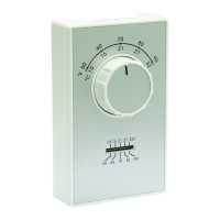
The Columbus Electric wall mounted line voltage thermostat is
suitable for direct connection with any resistance heating ele-
ments and unit heaters. This thermostat has a snap action switch
operated by a bimetal actuator and is available in single pole,
double pole with positive off, two stage heat. Cooling only and
heat or cool models. Other options include a built in thermome-
ter and/or 6 inch wire leads.
a division of TPI Corporation
If this product is used to replace a device containing mercury,
the purchaser or consumer must ensure that the mercury is
properly managed to comply with state or federal regulations.
e mercury must not become part of solid waste or waste
water. Additional guidance may be obtained from the manufac-
turer of the product being removed, or by calling
Columbus Electric Manufacturing Company Materials Manager.
INSTALLATION INSTRUCTIONS
Application: A vertical wall box is used for mounting thermostat
4 to 5 feet above the oor on an inside wall where the thermostat
will be subject to average room temperature. It should be away
from concealed warm or cold water pipes, warm or cold air
ducts, dras from hallways or stairways.
1. Disconnect power from source.
2. Remove cover from old thermostat.
3. Remove old thermostat by removing two screws.
4. Disconnect supply wires from old thermostat.
5. New installation: remove cover by gently pulling away from
thermostat.
6. Make connection of supply lead(s) (red) and load lead(s)
(black) using an approved connector (wire nut, crimp cap, or
etc.).
7. Connect the ground wire to the terminal marked “GRD” or
8. All wiring must conform to application code, ordinanances
and regulations in such matters as wire size, type of insulation
and enclosure.
9. Dress wires into wall box and secure your new thermostat to
the wall box with the screws provided.
10. Reinstall cover, select desired temperature and restore power.
SPECIFICATIONS
ELECTRICAL RATING
22 A Resistive @ 125/250/277 Vac.
3/4 HP @ 125 Vac.
1-1/2 HP @ 250/277 Vac.
DIFFERENTIAL
HEAT APPROXIMATELY:............. 2°F
COOLING APPROXIMATELY:..... 4°F
HEAT ANTICIPATOR MODELS:.1/2°F
TEMPERATURE RANGE DIMENSIONS
4-3/4” ....... HEIGHT
2-7/8” ....... WIDE
2-7/8” ....... DEPTH
SETTING RANGE......50°F TO 90°F
HEATING OR COOLING. 50°F TO 90°F
ATTIC FAN CONTROL.. 90°F TO 135°F
P/N: 8426
ECO# 1-7135
REV. -
LINE
HEATING AND COOLING
TWO STAGE
HEAT LOAD
COOL LOAD
LOAD 2
LOAD 1
LINE
LOAD
HEATING
DPST WITH ANTICIPATION
LINE
HEATING
SPST WITH ANTICIPATION
NO INTERNAL
CONNECTION
IN SWITCH
LOAD
LINE
LOAD
HEATING OR COOLING
SPST
LINE
HEAT LOAD
HEATING OR COOLING
SPDT
NORMAL OPEN
TERMINAL
COOL LOAD
NORMAL CLOSED
TERMINAL
LINE
LOAD
HEATING
DPST
YELLOW
WIRING DIAGRAMS