3
16”/406mm
F
A
B
A
B
PLEASE CHOOSE BEST INSTALLATION OPTION BASED ON TV BACK PANEL HOLE SPACING:
OPTION 1: 2.95 in x 2.95 in / 75 mm x 75 mm or 3.94 in x 3.94 in / 100 mm x 100 mm
21
3
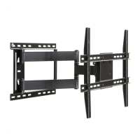
Remove TV mounting plate (B) from wall
bracket (A).
This mount is designed to be attached into wood
studs. DO NOT use wall anchors. Using a stud
pencil, mark the hole locations at the desired height,
making sure you are level. Use wall bracket (A) as a
template to mark the two remaining holes. Drill pilot
holes at 4 pencil marks 2.5 in. (64mm) deep, using a
3/16 in. or 5 mm diameter drill bit.
Attach wall bracket (A) to the wall with 4 washers and
screws (F).
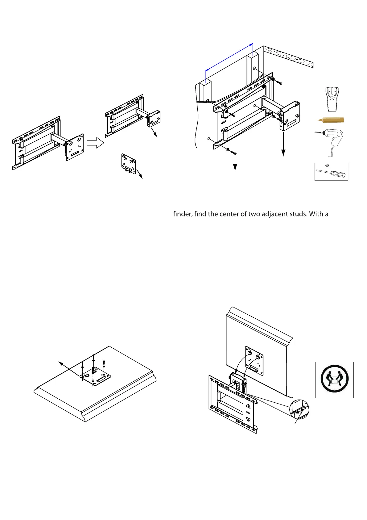
Attach TV mounting plate (B) to the back of
the TV, by selecting mounting hardware
and then using instructions on page 5.
We strongly recommend two people, one on each side,
hold the TV. Carefully position the TV over the wall
bracket (A) until it locks in place. Tighten safety screws.
4