Comba Telecom. All Rights
568 Gibraltar Drive, Milpitas, CA 95035 | +1 408 526 0180 Ext 3 | www.combausa.com
4
Version 1.0.4
1.16.23
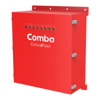
At the annunciator panel, connect the communication cable extension as shown below. Be sure to note RED (A),
BLUE (B) and BLACK (GND) when configuring the pigtail/extension to the phoenix connector located in the
annunciator panel.
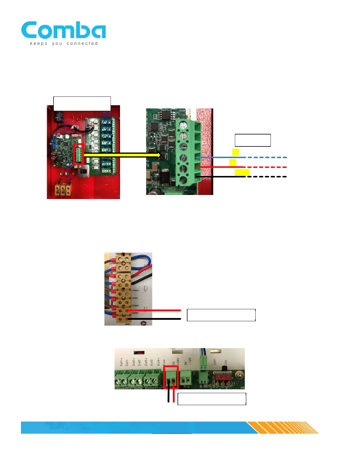
3. Power Cable
For BBU V1, the power will be provided from one of three LOAD outputs. Choose an open load output
and connect the power cable to the + and – ports. The same communications extension cable can be
used for power (for example, CAT5 cable, with 3 wires for communication and 2 for power).
For the BBU V2, power can be sourced from the MCU/control board 12VDC, 24VDC or Load Terminals
BLACK (GND)
RED (A)
BLUE (B)