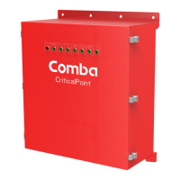
The Comba CriticalPoint Annunciator Panel is a crucial component designed to provide visual and audible alarm indications, primarily in conjunction with Comba's V1 or V2 Battery Backup Units (BBUs). It serves as a remote monitoring and notification device, ensuring that critical system statuses are promptly communicated to users. The panel's core function is to synchronize its dry contact alarms and visual annunciations with the BBU, making it an essential tool for maintaining system awareness and responding to potential issues.
Function Description:
The Annunciator Panel acts as an extension of the BBU's alarm system, offering a localized and immediate display of various operational statuses and fault conditions. It is powered and controlled directly by the BBU, requiring a three-wire communication cable for data exchange. This direct connection ensures that any alarm configured within the BBU is accurately reflected on the annunciator panel.
Key functional aspects include:
- Alarm Synchronization: The panel's dry contact alarms and visual annunciations are always synchronized with the BBU. This means that alarm configurations are managed centrally within the BBU, simplifying system setup and ensuring consistency.
- Audible Annunciation: An integrated audio buzzer provides an audible alert for alarms. This buzzer can be silenced, offering flexibility in managing notifications in different environments.
- Dry Contact Outputs: The annunciator panel features a duplicate set of dry contact outputs for alarms 1 through 7, mirroring those on the BBU. Additionally, it includes an eighth dry contact output (No. 8) that can be configured for specific purposes, such as monitoring the annunciator panel's integrity (communication fault alarm) or an over-temperature condition. This configurability is managed via the BBU's Graphical User Interface (GUI).
- Communication Fault Monitoring: The "Comm. Fault ALM" feature allows the panel to monitor the integrity of the communication circuit between the BBU and the annunciator panel. This is a critical feature for jurisdictions that require monitoring of dry contact alarm circuit integrity.
- Over Temperature Alarm: The panel can be configured to trigger an alarm if its internal temperature exceeds a predefined threshold, providing an additional layer of environmental monitoring.
- Dual Panel Operation: The system supports the use of two annunciator panels in parallel. In such configurations, the RS-485 A/B/GND communications circuit must be wired in parallel, and a DIP switch on the annunciator panel's circuit board is used to designate it as a primary or secondary unit.
Important Technical Specifications:
While specific detailed electrical specifications like current draw or exact voltage tolerances are not extensively detailed in the provided excerpts, the manual highlights critical operational parameters and connectivity requirements:
- Power Source: The annunciator panel is powered by the Comba V1 or V2 Battery Backup Unit.
- For BBU V1, power is supplied from one of the three LOAD outputs (+ and - ports).
- For BBU V2, power can be sourced from the MCU/control board's 12VDC, 24VDC, or Load Terminals.
- Communication Interface: A three-wire communication cable connects the annunciator panel to the BBU. The communication uses an RS-485 A/B/GND circuit.
- BBU V1: Uses a 3-pin header on the MCU/control board.
- BBU V2: Utilizes a three-slot phoenix connector on the MCU/control board.
- Cable Length (Communication):
- Max distance using 24-gauge wire: 2000 feet.
- Max distance using 18-gauge wire: 4000 feet.
- Firmware Requirements (BBU):
- BBU V1 (CPBBUV1-48055-UL): V8B01 or newer (Newest: V8E01).
- BBU V2 (CPBBUV2-48100-UL): V8101 or newer (Newest: V8501).
- Voltage Measurements (Troubleshooting):
- BBU V1/V2 (1->3 and 2->3): Approximately 1.65 VDC.
- Annunciator Panel (1->3 and 2->3): Approximately 1.65V ± 0.05V.
- Resistance Measurements (Troubleshooting - BBU disconnected):
- BBU V1:
- 1 to 3: ~450 Ohms
- 2 to 3: ~450 Ohms
- 1 to 2: ~50 Ohms
- BBU V2:
- 1 to 3: ~2.2k Ohms
- 2 to 3: ~2.2k Ohms
- 1 to 2: ~130 Ohms
- Annunciator Panel (data cables disconnected):
- 1 to 3: ~2.2k Ohms
- 2 to 3: ~2.2k Ohms
- 1 to 2: ~130 Ohms
- DIP Switch Configuration: A DIP switch (SW1) on the annunciator panel circuit board is used to configure the panel as a primary (1 OFF + 2 OFF = AP1) or secondary (1 OFF + 2 ON = AP2) unit when used in parallel. An invalid configuration (1 ON + 2 ON) results in an ERROR state.
Usage Features:
The Annunciator Panel is designed for straightforward integration and operation, providing clear indications and flexible control:
- Simple Cabling: The connection process involves a three-wire communication cable and a power cable, with clear instructions for connecting to both BBU V1 and V2 models. The manual emphasizes the importance of proper wire identification (RED (A), BLUE (B), BLACK (GND)).
- Software Configuration via BBU GUI: All alarm settings and panel configurations are managed through the BBU's GUI, specifically under the "Settings" and "Panel" tabs. This centralized control simplifies setup and maintenance.
- Panel Identification: The BBU GUI allows for the identification and activation of up to two annunciator panels, ensuring proper communication and alarm reporting for each.
- Alarm Silencing: The audio buzzer can be silenced by sliding a switch to the "ON" position. The audio will automatically un-silence after 24 hours, ensuring that persistent alarms are re-notified if not addressed. To re-silence, the switch must be moved to "OFF" and then back to "ON."
- Configurable Dry Contact 8: This output provides flexibility for system integrators to monitor specific conditions relevant to the annunciator panel itself, such as communication faults or internal temperature.
- Dev Info Display: The "Panel" page in the BBU GUI provides device information, including temperature, firmware version, and serial number, which is useful for diagnostics and inventory management.
Maintenance Features:
Maintenance of the Annunciator Panel primarily involves firmware updates and troubleshooting, both managed through the BBU system:
- Firmware Upgrade: The annunciator panel's firmware can be updated via the BBU GUI. This process involves uploading a new firmware file and initiating the upgrade, which then reboots the device. This ensures the panel remains up-to-date with the latest features and bug fixes.
- Troubleshooting Guide: The manual provides a detailed troubleshooting section for scenarios where the annunciator panel does not power on or appear in the BBU GUI. This includes step-by-step instructions for measuring voltages and resistances at specific points on both the BBU control board and the annunciator panel control board. These measurements help diagnose communication or power issues.
- BBU Firmware Dependency: The proper functioning of the annunciator panel is dependent on the BBU having the correct firmware version. The manual specifies the minimum required firmware revisions for both BBU V1 and V2.
- Communication Fault Alarm (DC8): The ability to configure Dry Contact 8 as a "Comm. Fault ALM" provides a proactive maintenance feature, alerting users to potential communication issues between the BBU and the annunciator panel before critical alarms might be missed.
In summary, the Comba CriticalPoint Annunciator Panel is a robust and integral part of a comprehensive emergency communication system, designed to provide reliable, synchronized, and configurable alarm notifications, with user-friendly features for installation, operation, and maintenance.