This document is an installation and operator manual for the ComCo Systems 521 Series, which includes various models of pneumatic tube systems designed for drive-thru applications. The manual provides detailed information on the system's features, operation, specifications, parts, installation, maintenance, and troubleshooting.
Function Description:
The ComCo Systems 521 Series are overhead pressure/vacuum pneumatic tube systems primarily used in drive-thru banking or similar environments. They facilitate the secure and rapid transfer of carriers containing documents, cash, or other small items between a customer unit (outside) and a teller unit (inside). The system operates by using a blower to create either pressure (to send a carrier) or vacuum (to recall a carrier) through a network of tubing.
Important Technical Specifications:
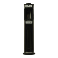
521A Teller Unit (TU) - Model: TU-521-201194:
- Dimensions: Approximately 6'-11" to 7'-1½" in height, with a base footprint of about 1'-1" x 1'-1". The unit is designed to be suspended from the ceiling, typically 10" above the countertop.
- Electrical Requirements: Requires a dedicated 120VAC 20AMP circuit to a standard duplex outlet located within 3 feet of the blower.
- Mounting: Utilizes a wall mount bracket and all-thread rods secured to the structure above for support.
- Components: Includes a system power switch, send button, and recall button.
Teller Unit (TU) - Models: TU-521-200501/200502 (Manual & Motorized):
- Dimensions: Approximately 5'-6 5/8" in height, with a base footprint of about 1'-2" x 1'-2". The cover length is about 4'-7 3/4". Designed to be suspended from the ceiling, typically 1'-2" above the countertop (40" height typical).
- Electrical Requirements: Similar to the 521A Teller Unit, requiring a dedicated 120VAC 20AMP circuit to a standard duplex outlet within 3 feet of the blower.
- Components: Features a system power switch, send button, and recall button, along with a System Power Indicator LED.
EZ Master Station - Model: TU-521-201057:
- Features: Ezy-Flow stations are constructed of 14 gauge CRS with a polyurethane finish. They feature a heavy acrylic, gasketed door with a positive latch and chrome handle for a tight seal. The integral air valve operates under pressure and vacuum, and is maintenance-free. All electrical components are accessible from inside the station.
- Standard Features:
- "In Use/Arrival" light: Glows green when ready, yellow when in use, and red upon carrier arrival until removed.
- Door interlock: Ensures the door is closed when the blower is running.
- Accommodates all carrier lengths.
- Uses low voltage wiring to connect stations and the blower unit.
- Optional Features:
- Photo-eye to detect carrier presence.
- Audible signal for carrier arrival.
- Electrical Requirements: Dedicated 120VAC 20AMP circuit to a duplex outlet in the canopy for blower power (within 3ft of blower). An additional 120VAC 20AMP dedicated circuit to a duplex outlet in the canopy for video power (optional in island).
Customer Unit (CU) - Model: CU-521-200500:
- Dimensions: Designed for outdoor installation, typically mounted on an island.
- Electrical Requirements: 12 VDC, 1.2 amps (for the Customer Video Module CV-100-200203).
- Components: Includes a send button and a call button.
- Optional 2-Way Video: Can be integrated with a 2-way video system (P/N: 200500).
Single Pack Blower Module - Model: BM-200-200217:
- Function: Provides the pressure/vacuum necessary for carrier movement.
- Electrical Requirements: Requires a dedicated 120VAC 20AMP circuit within 3.0 ft of the unit. All line power must comply with NEC.
- Fuses: Equipped with a 2-115 VAC 10A resettable fuse, a 1-115 VAC 0.5A resettable fuse, and a 1-24 VAC 1.5A resettable fuse.
- Mounting: Must be installed in a horizontal orientation. If in a closed canopy, the exhaust port must be vented to outside air to prevent overheating.
- Circuit Breakers: Equipped with 10-amp circuit breakers to protect motors from overload.
Carriers:
- Type: 4 1/2" Carrier (P/N: 602033) end-opening.
- Weight: Must not exceed 4 lbs.
- Components: Air ring – 4.25 3-ply – 4.50 EO carrier (P/N: 602013), Wear band - Velcro – 4.5" (2 per carrier) (P/N: 602052).
Usage Features:
Teller Unit (521A, 521, 521 EZ Master Station):
- ON/OFF: Power cycles the complete system (Inside Unit, Outside Unit & Blowers). Power ON illuminates the system power light. Power OFF shuts down the entire system, including the Customer Video Module (CVM) if installed.
- SEND: Sends a carrier to the customer unit.
- RECALL: Recalls a carrier from the customer unit.
- Theory of Operation (Power ON):
- Teller switches power ON.
- Power indicator illuminates.
- Automatic Teller Units only: Teller Unit door opens.
- CVM Systems only: Camera and monitor in CVM are powered ON.
- System is now in ready state.
- Theory of Operation (Power OFF):
- Teller switches power OFF.
- Power indicator extinguishes.
- Automatic Teller Units only: Teller Unit door closes.
- CVM Systems only: Camera and monitor in CVM are powered OFF.
- System is now OFF.
- Theory of Operation (Send Cycle):
- Teller inserts carrier into teller unit.
- Manual Teller Units only: Teller closes teller unit door and Send cycle begins.
- Automatic Teller Units only: Teller presses SEND and Teller Unit door closes.
- Send cycle begins.
- Pressure blower activates.
- The check valve in the Valve bend opens and the relief valve closes, sending air pressure to Teller Unit.
- Carrier is propelled from Teller Unit into transmission tubing, towards Customer Unit.
- Carrier activates Deceleration Trigger – ending send cycle (Note: if deceleration trigger is not activated, the cycle timer times out and send cycle ends, but steps 10 & 11 do not occur).
- Pressure blower deactivates.
- Stop Valve is activated by stop solenoid, blocking air behind carrier (simultaneous to step 9).
- Carrier decelerates due to vacuum behind carrier.
- Carrier arrives at Customer Unit.
- System is now in ready state.
- Theory of Operation (Recall Cycle):
- Customer inserts carrier into Customer unit.
- Customer presses SEND.
- Recall cycle begins.
- Vacuum blower activates.
- The check valve in the Valve bend closes and the relief valve opens, pulling vacuum from Customer Unit.
- Carrier is pulled from Customer Unit into transmission tubing towards Teller Unit.
- Carrier passes relief valve.
- Carrier is decelerated by pressure ahead of carrier (check valve in Valve Bend blocks pressure from Teller Unit).
- Carrier arrives at Teller Unit.
- Recall timer times out.
- Automatic Teller Units only: Teller Unit door opens.
- Manual Teller Units only: teller opens Teller Unit door.
- Recall cycle ends – system is now in ready state.
Customer Unit:
- SEND: Sends carrier to Teller Unit. (Note: Do not insert loose items directly into unit).
- CALL: Generates an audible tune at the Teller Center when depressed.
Maintenance Features:
Blower Unit:
- Overload Protection: Equipped with 10-amp circuit breakers. If the system fails to run, check if either circuit breaker has tripped.
- Troubleshooting: If circuit breakers trip regularly, an authorized service agent should diagnose the problem. If SEND or RECALL lights but the blower fails to run, confirm the door is fully closed.
Deceleration Trigger Bend:
- Inspection: Essential for proper system performance. Inspect regularly for cracks, wear, or missing parts.
- Replacement: If cracked, worn, or missing, it must be replaced immediately.
- Switch Assembly: The deceleration switch assembly has 4 switches, with only one required for proper operation. If inoperable, the assembly must be replaced immediately.
Carriers:
- Inspection: Inspect regularly for signs of wear.
- Replacement: Worn air discs or rubbing bands can cause carriers to land hard at either unit and should be replaced as required.
Teller Unit:
- Cleanliness: Guard against dropping debris into the teller unit while cutting holes and during installation. The teller unit door assembly must be kept clean for proper operation. It is recommended to cover the top of the teller unit with paper or plastic during construction and vacuum the bottom of the door track after installation.
- Timer Adjustment: Adjust timer T1 for approximately 5 seconds greater than the time required for an empty carrier to be recalled from the customer unit to the teller unit (typically 2-3 seconds after the carrier lands at the teller unit).
Tubing:
- Sealing: All tubing joints must be properly sealed, especially at the teller and customer units.
- Deburring: All inside edges of tube joints must be de-burred and ground to an angle to prevent excessive wear on carriers.
Return Material Authorization Procedure:
- To return items for repair, customers must call ComCo Systems to request an RMA# (Return Materials Authorization number) or email PARTS@COMCOSYSTEMS.COM.
- Required information includes Company Name, Phone Number, Contact Person, Store#, Component(s) being returned, Description of problem, and Serial number of product.
- Returns without an assigned RMA# will not be accepted.
- Status of an RMA can be checked via email or by calling Customer Service Representatives.