Parameter Symbol Description
Configuration Parameters
(These parameters are part of Configuration level)
Input Type
inP
Type of signal that can be connected to the device input
Unit
unit
Temperature measurement unit
Point Position
Pnt
Display decimal point position
Input Low
ILo
Display value at low limit of the linear input range
Input High
IHi
Display value at high limit of the linear input range
Input Correction
Constant to be added to the measured input value
Address
Addr
Device address
Baud Rate
bAud
Serial interface rate
Gradient
GrAd
Maximum input signal change during the sampling period (120 ms)
Filter Time
\t
Relative time constant of the input filter
Filter Band
\b
Zone around the measured value, within which the filter is active
SP limit Low
%[L
Set-point Low limit
SP limit High
%[H
Set-point High limit
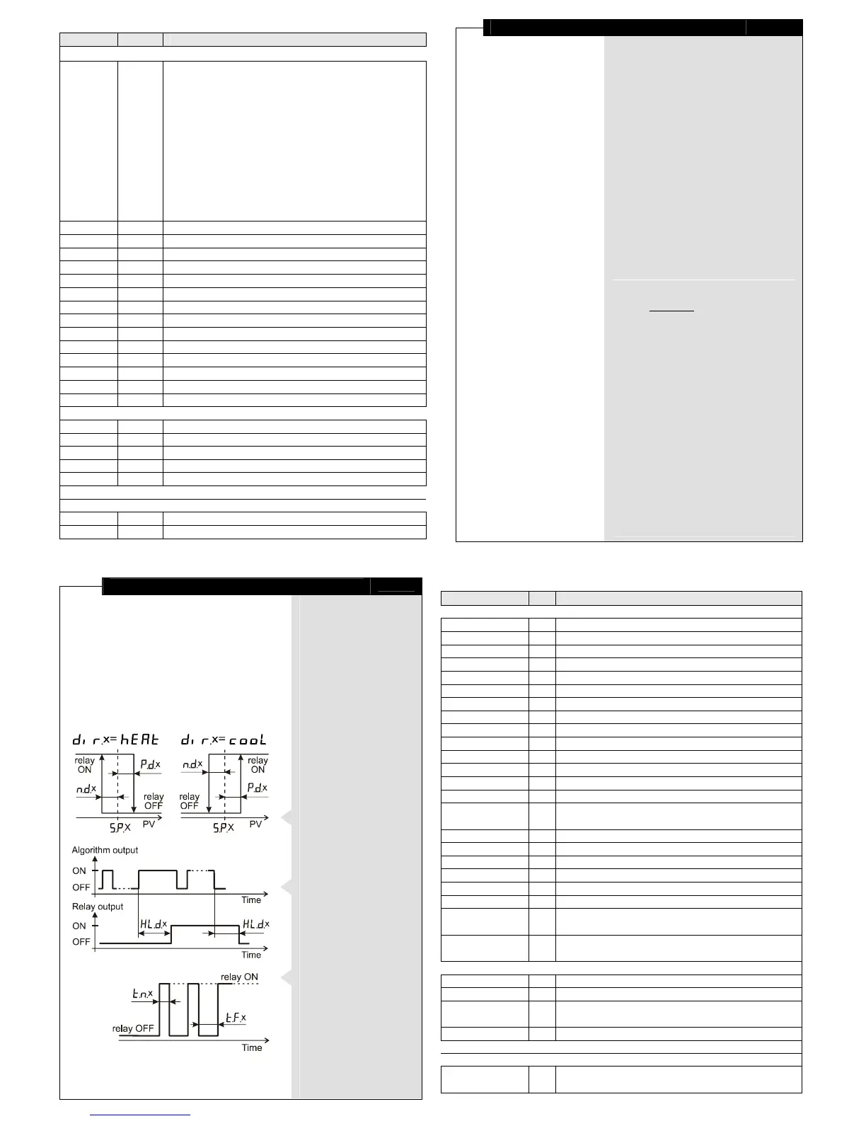
Direction 1
diR1
Control action direction of output K1
Direction 2
diR2
Control action direction of output K2
Parameters of the control algorithm
(These parameters are part of Parametric level)
+ Differential 1
[e1
Positive Differential of output K1
- Differential 1
me1
Negative Differential of output K1
Time On 1
ym1
ON duration of output K1
Time Off 1
y\1
OFF duration of output K1
Hold 1
HLe1
Holds the output reaction of output K1
The same 5 parameters, but with index 2 - for output К2
Parameters of Basic (operating) level
Set-point value of output K1
Set Point 2
%[2
Set-point value of output K2
Input Filtration
11
Peak filter
This filter is intended for eliminating
pulse spikes (peaks), which can appear
in the input signal, in the following way:
♦
RT284U measures the input signal
value every 120 ms (sample time).
♦
The measured values are compared
subsequently. The filter checks
the difference between the last
two samples. If it does not exceed
Gradient value, the device accepts
the signal as normal.
♦
If the last measured value differs
from the previous one by more than
the Gradient value, the filter output is held
until the device determines a presence
of a normal signal. It is possible only
if the input signal has not been changed
with more than the Gradient value
for four subsequent samples.
♦
If the device has not determined
a normal signal for 20 subsequent
samples, noiS appears on the display
(see 'Basic level').
Low-pass filter
This first-order filter acts ONLY within
a certain band around filter output value.
This has been designed to cut periodic
noises outside the communication signal
spectrum.
♦
Filter operation is defined by two
parameters:
Filter Time
(defines filter time constant) and
Filter Band
(defines filter active band
around filter output value).
♦
If the newly measured value differs
from the filter output by more than
Filter Band, the filter resets
with a new initial output value
(newly measured value).
Output Control
10
Control output operation
♦
The control outputs
operate according
to the control algorithm
parameters.
♦
The outputs deactivate
with the value change
of one of the following
configuration
parameters - Point
Position, Input Low, Input
High, and Input Correction
- and remain inactive till
Basic level is entered.
♦
The outputs deactivate
also when an error
has been detected
(see
'Error messaging').
ON/OFF control algorithm
The static characteristic
of a relay controlled
by an ON/OFF algorithm
is shown on the left drawing.
Output hold
For eliminating undesirable
switches of the relay output,
additional parameter (Hold)
is assigned to hold
the output reaction
for certain period of time.
Output pulse mode
When a relay is forced
to ON by the control
algorithm, it can either
stay ON or pulse
depending on Time On and
Time Off parameter values.
Setting any of these
parameters to '0'
disables the Pulse mode.
Table 1
Value Unit
Notes
Pyh or Pyt - Pt100: -100…850 °C or Pt1000: -100…600 °C
Ptx1 or Ptx2 - PTC 1k or 2k: -50...150 °C
R)1
- resistive linear: 0…1 kΩ
yc-b
- T/C "B": 200...1800 °C
yc-J
- T/C "J": -20...1000 °C
yc-"
- T/C "K": -20...1300 °C
yc-r
- T/C "R": 0...1700 °C
yc-S
- T/C "S": 0...1700 °C
yc-t
- T/C "T": -40...400 °C
u
- voltage linear: 0…100 mV
I)20 or I$20 - current linear: 0…20 mA or 4…20 mA
w)10
- voltage linear: 0…10 V
.Cor .F - °C or °F
x1, x0.1, x0.01, x0.001 - when indicating values with the input-signal measurement unit (ISU)
-1999 ... 9999 ISU These parameters make sense ONLY in case of a linear input signal!
-1999 ... 9999 ISU OFFSET
1…254 -
!2, @4, $8, (6 bps 1200, 2400, 4800 (factory-set), or 9600 bps
0 … 9999 ISU used for input peak filtration; Value '0' cancels the filtration.
0 … 9999 - This parameter and the following one define a low-pass input filter.
0 … M ISU
temperature: whole part of M ≤ 100; linear: M = 25% of input range
within input range ISU
These parameters keep the Set point in safe limits,
preserving it from random changes.
cooL, hEAt - ('cooling' , 'heating')
These parameters are accessible in the presence of the corresponding relay.
0 ... 9999 ISU lower than (High input range - Set Point 1)!
0 ... 9999 ISU lower than (Set Point 1- Low input range)!
0 ... 9999 sec. Value '0' disables Pulse mode.
0 ... 9999 sec.
These parameters are accessible in the presence of the corresponding relay.
within input range ISU
 Loading...