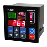
The TC800 is an eight-channel indicator/controller designed for indicating, monitoring, and controlling various technological variables. It can be used as a multi-channel limit monitor, a two- or three-state ON/OFF controller, or a multistage controller.
Function Description:
The TC800 measures input values, compares them with predefined set-point values, and switches relays accordingly. It supports up to 8 analog inputs and can be configured for various sensor types including thermoresistance (RTD), thermocouple (T/C), linear voltage, and linear current inputs. The device features 16 alarm limits (limit comparators) that can be assigned to any input and activate up to 8 relay outputs. It also includes a K9 relay for system failure signaling. The TC800 can operate in Auto, Pseudo-manual, and Manual modes. In Auto mode, it cyclically displays measurements from all enabled inputs. Pseudo-manual mode allows for manual selection of the displayed input while continuing to monitor all alarms. Manual mode configures the device as a single-channel indicator/controller, measuring and monitoring alarms only for the currently displayed input.
Important Technical Specifications:
- Inputs: Up to 8 analog inputs, supporting RTD (Pt50, Pt100, Pt500, Pt1000, Cu50, Cu53, Cu100, Ni100), T/C (NiCr-Ni, Fe-CuNi, Pt10%Rh-Pt, Pt13%Rh-Pt, NiCr-CuNi, Cu-CuNi), linear voltage (0...2V, 0...5V, 0...10V), and linear current (0...20mA, 4...20mA, 0...50mA).
- Outputs: Up to 8 programmable relay outputs (electromechanical relay or solid-state relay) and an auxiliary supply output (max. 40 mA).
- Digital Interface: RS485 with ASCII and Binary protocols.
- Measurement Error: 0.4% from span.
- Temperature Drift: 0.005% from span per 1 °C.
- Cold Junction Compensation: ± 1 °C, automatic software.
- RTD Line Compensation: Software-based.
- Relay Specifications: Electromechanical relay (max. 250 V, 3 A, NO/NC), solid-state relay (max. 250 V AC, 1 A), MOS gate (max. 60 V, 0.1 A, optically isolated), output for external SSR (5...24 V, max. 30 mA).
- System Alarm: 1 system alarm with electromechanical relay (max. 250 V, 3 A, NO/NC).
- Display: Front panel LEDs for input number, measured value, and alarm status.
- Power Supply: Main power supply and transmitter power supply.
Usage Features:
- Operation Modes:
- Auto Mode: Cyclically displays measurements from all enabled inputs.
- Pseudo-manual Mode: Allows manual selection of the displayed input while all alarms are still monitored. Indicated by an "=" sign next to the input number.
- Manual Mode: Functions as a single-channel indicator/controller, measuring and monitoring alarms only for the currently displayed input. Indicated by a blinking "=" sign next to the input number.
- Alarm Configuration: Up to 16 alarm limits can be configured with upper/lower limit, window, and inverted window alarm types. Each alarm can be assigned a relay output, hysteresis, and hold time to prevent undesirable switching.
- Input Skipping: Users can select inputs to be skipped from the Auto-mode display sequence while still being measured and having their alarms function.
- External Switching: Discrete input 1 can be used for remote switching of displayed input channels or to change the operation mode from Auto to Pseudo-manual.
- Password Protection: Parameters can be protected from unauthorized access using a password.
- Parameter Programming: Parameters are organized into groups (CONFIGURATION, FAILURE STATES PROGRAMMING, DEFAULT THERMOCOUPLE COLD-JUNCTION TEMPERATURE, INPUT CYCLING CHANGE RATE, SKIPPING OF SELECTED INPUTS, and INFORMATION) for structured access and modification.
- ON/OFF Control: The device can be programmed to function as an ON/OFF controller by setting alarm parameters (ALL, HYST, TYPE) to control a relay based on a set-point value.
- Duplex ON/OFF Control (Heating & Cooling): Two relays can be used for heating and cooling control, with dead band (DB) configuration to prevent simultaneous activation.
Maintenance Features:
- Self-Test: The device performs a self-test on power-on, checking LEDs and display indicators.
- Error Messages: Various failure messages (e.g.,
conF for configuration, AL ## for alarm number, Fi for sensor failure, Er for programming exit error, FL for parameter group exit error) are displayed to indicate issues.
- Parameter Value Validation: During programming, the device checks if new parameter values are within allowed limits. If not, an error message (
L for too small, Γ for too big) is displayed.
- Parameter Group Programming Completion: All changes within a parameter group are stored permanently only after the group programming is explicitly finished. If not completed or if there are unacceptable values, changes are not saved.
- Power-Down/Electromagnetic Disturbance Handling: In case of power-down or strong electromagnetic disturbance, group programming is automatically exited, and no parameter changes are saved.
- Mounting: Select a mounting location away from strong electrostatic or magnetic fields, and protected from excessive heat and moisture. The device fits into a 90x90 mm panel cut-out.
- Wiring: Uses plug-in terminals for easy wiring of analog inputs, discrete inputs, relay outputs, digital interface, and power supplies.
- High-Voltage Spike Suppression: Recommendations include connecting a metal-oxide varistor (MOV) in parallel with inductive loads and an RC network in parallel with contacts to suppress high-voltage spikes and prolong contact life.
- RTD Line Resistance Compensation: The device allows defining line resistance for RTD inputs to ensure accurate measurements.