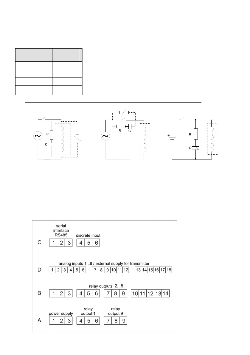
To suppress high-voltage spikes, connect a metal-oxide varistor (MOV) in parallel with and as closer
as possible to the inductance (Fig. 3.2). An RC network in parallel with the varistor is highly recommended.
It should constitute of a 220 Ω resistor in series with a 0.5 μF / 1000 V capacitor. Select resistor power in relation
to the inductance voltage. Always use wire wound or carbon resistor. Keep RC network leads short.
When a contact opens and breaks inductive load circuit, a certain amount of
energy stored in the inductance has to be released. This causes both
electromagnetic interference and contact life shortening. To 'quieten' the
arc, connect an RC network in parallel with the contact (Fig. 3.3). For
circuits up to 3A / 300 V, the RC network should be made of a 47 Ω
resistor in series with a 0.1 μF / 1000 V capacitor. In cases of voltages
higher than 200 V, add MOV in parallel.
Please note that at 230 V, 50 Hz supply, up to 7 mA current may flow through the network.
Fig. 3.2 Fig. 3.3 Fig. 3.4
In parallel with the inductive load, connect a network consisting of a diode in series with a resistor. Mind that
the resistance should be less than that of the inductive load (Fig. 3.4).
3.2. Mounting
Select mounting location far from strong electrostatic or magnetic fields and protected from excessive heat
and moisture to ensure normal device operation. Place the device into a 90x90 mm panel cut-out and tightened
into place using the enclosed mounting brackets.
 Loading...