Do you have a question about the Comelit 1404 and is the answer not in the manual?
Product designed for audio/video communication systems in residential, commercial, industrial, and public buildings.
All installation activities must be performed by qualified technical personnel, following manual indications.
Disconnect power before wiring; use suitable wires and avoid routing with power cables.
Observe manual instructions and ensure system integrity to guarantee safe product usage.
Products require minimal maintenance; repairs must be done by Comelit or qualified personnel.
Comelit disclaims responsibility for misuse and reserves the right to change information without notice.
Configure the device for standard operation using DIP switches for zone address management.
Set up the device for TOP 1 mode, defining system area and zone addresses.
Configure the device for TOP 3 mode to manage multiple zones within a set range.
Diagram for a single-family kit using standard mode with two inputs.
Diagram for a single-family kit using standard mode with three inputs.
Wiring diagram for systems using Art. 1210/1210A in standard mode with two inputs.
Diagram for Art. 1210/1210A systems in standard mode with one main and two secondary inputs.
Layout for Art. 1210/1210A systems in TOP1 mode with branched kits and external units.
Configuration for Art. 4888C systems in TOP1 mode, featuring branched kits and cascade setups.
Wiring diagram for Art. 1210/1210A systems in standard mode with kits arranged in cascade.
Diagram for Art. 1210/1210A systems in TOP1/TOP3 modes with multiple main and secondary units.
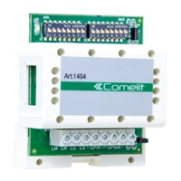
The Comelit Art. 1404 is a digital switching device designed for use in Simplebus 2 audio and video communication systems, particularly in installations with multiple entrances. It serves as a crucial component for managing and distributing signals within residential, commercial, industrial, and public buildings.
The Art. 1404 acts as a switching device that enables the expansion and organization of Simplebus 2 systems. It supports three primary operating modes:
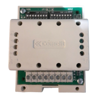
The device features a DL1 indicator LED:
Dip-Switches S1 and S2 are used for setting the range of user or zone addresses. Dip-Switch S3 controls the operating mode (DIP1, DIP2) and zone address management (DIP3). DIP4 of S3 manages the connection on the LS line, with OFF for external units on the LS section (default) and ON when no external unit is on the LS section (requiring a power supply unit Art. 1209 or Art. 1210/1210A). If there is no secondary external unit, DIP4 should be set to ON.
Terminal block M1 includes:
JP1 jumper is for video closure:
The Art. 1404 must be wired with Art. 1209/1210/1210A or exiting the mixer Art. 4888C. The maximum number of switching devices Art. 1404 that can be connected to Art. 1210/1210A or Art. 4888C is 40 units.