CONTENTS
•
GENERAL INFORMATION
5
•
TECHNICAL SPECIFICATIONS
5
• PROGRAMMING AND OPERATION
1) Entering the supercode
2
) Relay codes: first programming
3
) Using relay codes
4
) Cancelling relay codes
5) Bistable/Monostable operation
6
) Anti-coercion function
7
) Programming the allowed errors number
8
) Programming the relay 1 activation delay for a remote key input
5
5
5
6
6
6
6
6
6
•
ENABLING THE “KEY” BUTTON
6
• RESET INPUT 6
• REMOTE KEY INPUT (RK) 6
•
TERMINAL BLOCK - DESCRIPTION
6
CONNECTION DIAGRAMS:
•
CA/A “POWERCODE” electronic key system.
1
7
•
CA/B “VANDALCODE” electronic key system.
1
7
•
VCC/01B/PC “POWERCODE” electronic key system in traditional
cabling video door entry system.
18
•
C5/01S/PC “POWERCODE” electronic key system in traditional
c
abling door entry system.
1
9
• SB2V/01B/PC “POWERCODE” electronic key system in Simplebus 2
cabling video door entry system. 20
• SB2V/01PX/PC “POWERCODE” electronic key system in Simplebus
Color cabling video door entry system. 21
• SBC/01S/PC “POWERCODE” electronic key system in Simplebus
c
abling audio door entry system.
2
2
•
C5/AAD “VANDALCODE” electronic key in traditional cabling
a
udio system.
2
2
•
VCC/AAB “VANDALCODE” electronic key in traditional cabling
v
ideo door entry system.
2
3
•
SB2/ABD “VANDALCODE” electronic key in Simplebus,
S
implebus 2, or Simplebus Color cabling system.
2
3
•
Using the RC network for lock filter on relay 1 and 2 contacts.
2
4
GENERAL INFORMATION
T
he “POWERCODE” electronic key system consists of 2 models:
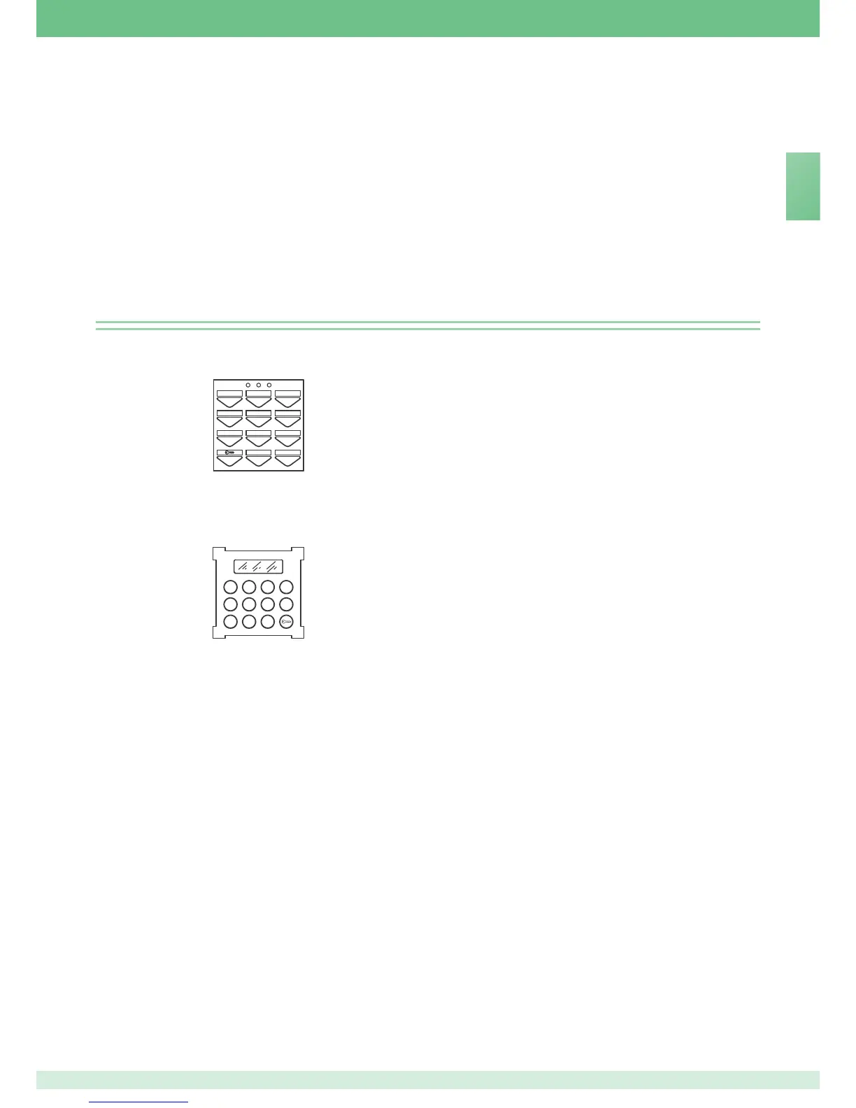
• Art. 3328 for mounting in Powercom modular keypads for mixed access control
-
entry panel - video entry panel installations or stand-alone applications.
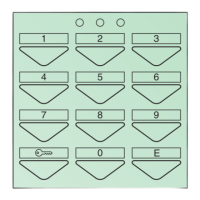
• Art. 3188 for mounting in Vandalcom modular keypads for mixed access
control - entry panel - video entry panel installations or stand-alone
applications.
In technical terms, Art. 3328 and 3188 include 2 controllable relays with
different codes.
Art. 3188
TECHNICAL SPECIFICATIONS
• 302 total available codes:
- one supercode;
- 300 relay codes. The available codes can be distributed in any way between
relay 1 and relay 2. Example: 245 different codes for relay 1, and 55 different
codes for relay 2;
- one anti-coercion code.
• Available outputs:
2 on independent relays, plus 2 open collector (1 for Art. 3328).
• Operation of the relay outputs: keypad programmable, mono- or bistable.
• Monostable mode: pulse programmable from 1” to 99” approx.
• Supercode: 1 to 8 repeatable digits.
• Relay codes: 1 to 8 repeatable digits.
• Anti-coercion code: 1 digit.
• Remote reset input (Art. 3188 only).
• Remote key input.
• Programming input.
• Single-key operation mode input (timetable programmer).
• 3 LED’s, depending on model:
2 to indicate relay closure and 1 to indicate programming mode.
• Outputs (NO-NC), potential free.
• Contact capacity: 24V AC/DC MAX.
• Service output: max 500 mA.
• Power supply: 12V AC/DC.
• Power Consumption: 250 mA 12V AC with 3 relays active.
• Operating temperature: -10°C to +50°C.
PROGRAMMING AND OPERATION
T
here is a timeout for programming procedures after which the operation is
c
ancelled (around 40” between successive keystrokes); we recommend
familiarising yourself with the procedure before starting it.
1) Entering the supercode
P
rogramming the supercode is the first operation, because all subsequent
steps depend on it.
We recommend using a short, easy to remember supercode, or noting it down on
a sheet of paper.
Entering the supercode
1
) Power up the key which has been cabled but is still open.
2
) Insert a jumper between PGM and the negative (- or ck2 ).
3
) Check that the red LED has lit up.
4) Enter the supercode (1 to 8 digits).
5) Press “E” to store the code.
6) Wait for 10 seconds or for the confirm tone to sound.
7) Remove the jumper.
Example:
to enter supercode 12345, proceed as follows:
- power up;
- fit the jumper;
- enter in sequence 1 2 3 4 5 E;
- wait for 10 seconds or for the confirm tone to sound; remove the jumper.
• If you make an error in entering the code, press the “key”
A button
several times to cancel the operation.
• You must always enter “E” at the end of the operation, whether during
programming or normal use.
• Modifying or changing the supercode resets all other programmed
settings (including relay codes).
• The supercode cannot be reset to a default value, but only replaced.
2) Relay codes: first programming
To program the relay codes, you must first know the supercode. The red LED on
the keypad stays on during the programming procedure.
In case of error, it flashes briefly and then turns off, after which you must start
again from the beginning of the procedure.
Relay codes: first programming procedure
1) Enter “0” and “E” (start programming procedure code).
2) Check that the red LED has lit up.
3) Enter the supercode (entered in point 1) followed by “E”.
4) Enter the relay ID number (1 or 2) followed by “E”.
5) Enter the operating mode (see point 5), then “E”.
6) Enter the new code followed by “E”.
7) The LED should now turn off.
Example:
To enter code 55127 for relay 1 in bistable mode (on/off), make the following
keystrokes:
0E start procedure
12345 E supercode
1 E relay 1 ID
O E bistable operating mode
55127 E new code
5
ENENENEN
 Loading...