EasyManua.ls Logo

Comelit 8171IPL User Manual

Comelit 8171IPL
116 pages
Go to English
To Next Page IconTo Next Page
Page #1 background imageLoading...
Page #1 background image
Assistenza tecnica Italia 0346/750090
Commerciale Italia 0346/750091
Technical service abroad (+39)0346750092
Export department (+39) 0346750093
www.comelitgroup.com
PT
MANUAL
TÉCNICO
IT
MANUALE
TECNICO
EN
TECHNICAL
MANUAL
FR
MANUEL
TECHNIQUE
NL
TECHNISCHE
HANDLEIDING
DE
TECHNISCHES
HANDBUCH
ES
MANUAL
TÉCNICO
Manuale tecnico Planux kit monofamiliare Art. 8171IP, 8171IPL
Technical manual for single-family Planux Kit Art. 8171IP, 8171IPL
Manuel technique Planux kit un usager Art. 8171IP, 8171IPL
Technische handleiding Planux kit eengezinswoning Art. 8171IP, 8171IPL
Technisches Handbuch Planux Kit Türsprechanlage
für Einfamilienhaus Art. 8171IP, 8171IPL
Manual técnico Planux Kit unifamiliar art. 8171IP, 8171IPL
Manual técnico Planux Kit monofamiliar art. 8171IP, 8171IPL

Table of Contents

Question and Answer IconNeed help?

Do you have a question about the Comelit 8171IPL and is the answer not in the manual?

Comelit 8171IPL Specifications

General IconGeneral
Connectivity/TechnologyIP
Power SupplyPoE (Power over Ethernet)
CameraYes
Weight1.2 kg
IP RatingIP54
TypeVideo Intercom
AudioFull-duplex
MountingWall Mount
Night VisionYes
Operating Temperature-10°C to +55°C

Summary

General Information and System Overview

External Unit Components

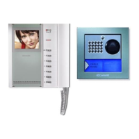
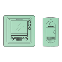
Details about external units like Art. 4878KC and their installation.

Internal Unit Components

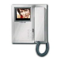
Details about internal units like Art. 6101/6114KC and Art. 2608.

Installation and Operation Guides

Instructions for general installation, operation, and settings.

Wiring Diagrams Overview

Introduction to various connection diagrams for system configurations.

External Unit Details and Specifications

Terminal Block Description

Explains the functions of each terminal on the unit.

Art. 4878KC Technical Specifications

Details on connections, camera, nameplates, and volume control.

Art. 1207 Power Supply Unit Specs

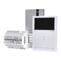
Information on the transformer's power outputs and dimensions.

External Unit Installation Steps

Guided process for installing the external unit.

Nameplate LED Lighting Selection

How to select lighting for nameplates.

External Unit Installation Procedures

Mounting and Microphone Adjustment

Steps for mounting and adjusting the microphone position.

Nameplate Insertion Guide

Visual guide for correctly inserting nameplates.

Internal Unit Features and Controls

Art. 6101-6101/C Monitor Specifications

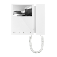
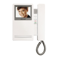
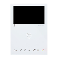
Technical details and component list for the colour monitor.

Key Functions and Programming

Explanation of programmable keys, privacy/doctor functions, and navigation.

Door Entry Monitor Key Operations

How to use audio, door lock, and programmable keys.

Mounting Art. 6101-6101/C with Flush-Mounted Box

Mounting Art. 6101 with Low Wall-Mounted Box

Installing the Art. 2608 Door-Entry Phone

Art. 2608 Device Overview

Description of the door-entry phone, its functions, and indicators.

Installation Procedures for Art. 2608

Step-by-step visual guide for installing the device.

System Installation and Operation

Operating Distances and Cable Specifications

Table detailing maximum distances based on cable type.

System Operation Guidelines

Information on call handling, conversation duration, and system feedback.

Button Functions and System Settings

Bracket and Door-Entry Phone Settings

How to configure dip switches for call addresses.

Function Descriptions

Explains self-ignition, video request, and internal call functions.

Managing Additional Monitors

Guidelines for configuring main and secondary monitors.

Programming Planux Monitor Keys

Programming Key 1 and Key 2

Steps to program keys for functions like actuators or self-ignition.

Programming and Disabling Key Functions

Configuration for privacy, doctor, or actuator functions.

Programmer Menu Operations

Accessing the Programmer Menu

Procedure to enter the system's programming menu.

Configuring Actuator and Camera Codes

Steps for setting codes for actuators and cameras.

Key Tone Enable/Disable Settings

How to manage auditory feedback for key presses.

System Configuration and Reset

Programming Multiple Addresses

Assigning additional codes for internal units.

Customizing Multiple Address Melodies

Setting specific ringtones for multiple addresses.

System Reset Procedure

Steps to restore the system to its original factory settings.

System Integration and Settings

Activating Multiple Address Features

Steps to enable and use multiple address functionality.

Changing System Menu Language

How to select the desired language for the user interface.

Main Entrance Kit Integration

Connecting the kit to main entrance panels using specific art. numbers.

Programming Art. 4680KC Buttons

Configuring buttons on the main entrance unit.

Special Programming for Art. 4680KC

Dip Switch Settings for Functions

Detailed table for configuring functions via dip switches.

Actuator Control Management

Settings for controlling actuators via the unit.

System Function Settings

Configuration options for response times and self-ignition.

Basic Wiring Diagram PXK/012IC

PXK/012IC Single-Family Kit Diagram

Base diagram for single-family kits with voltage checks.

Diagram PXK/017IAC

PXK/017IAC Kit Diagram with Second Unit

Diagram for kits extended with a second external unit.

Diagram PXK/012I/AC

PXK/012I/AC Diagram with Additional Power Supply

Wiring diagram for kits with an extra power supply unit.

Diagram PXK/015IC

PXK/015IC Remote Camera Module Diagram

Connection diagram for using a separate camera module.

Diagram PXK/EN/107IC

PXK/EN/107IC Main Entrance Diagram

Diagram for connecting 2-9 kits to a main entrance panel.

Art. 4680KC Operating Restrictions

Limitations for using Art. 4680KC with digital or button modules.

Diagram PXK/EN/108IC

PXK/EN/108IC Cascade Connection Diagram

Diagram for connecting up to 30 kits in cascade via Art. 1424.

Video Amplifier and Parallel Monitor Connections

SB2/AAR Video Amplifier Connection

Diagram for connecting the video amplifier Art. 4833C.

PXK/HC Main Monitor Cascade Connection

Diagram for adding a main monitor in parallel via cascade.

Monitor Connection Variations

PXK/IC Main Monitor Branch Connection

Diagram for connecting a main monitor in parallel via branch.

PXK/AAC Third Monitor Cascade Connection

Diagram for cascade connection of a third main monitor with local power.

Multi-Monitor Connection Configurations

PXK/A9C Branch Connection for Monitors

Diagram for branch connection of main and secondary monitors with the same user code.

PXK/CC Cascade Connection for Monitors

Diagram for cascade connection of main and secondary monitors with the same user code.

Additional Intercom Connections

PXK/AAE Additional Intercom Branch Connection

Diagram for branch connection of additional intercoms from the monitor.

PXK/AAD Additional Intercom Cascade Connection

Diagram for cascade connection of additional intercoms from the monitor.

Parallel Intercom and Button Usage

PXK/FC Parallel Intercom Connection

Diagram for adding a parallel intercom via branch connection.

SB/X3 Button P1 Usage

Instructions for various uses of button P1 on Art. 2608.

Call Repetition Device Connections

PXK/AAK Call Repetition Device Setup

Connecting call repetition devices Art. 1229/1122/A and unit limits.

Cable Length and Load Considerations

Recommendations for screened cables and inductive loads.

Actuator Relay Connections

PXK/EC Actuator Relay Art. 1256 Wiring

Diagram for connecting the actuator relay Art. 1256.

Power Supply Notes for Art. 1256

Important information regarding power supply for the actuator relay.

External Unit Relay and Security Variants

PXK/RTNP External Unit Relay Usage

Using the external unit relay for lock-release or actuator control.

PXK/SNP Security Lock and Power Supply Variant

Diagram for a variant with a security door lock and extra power.

Door Lock Filter and Door Open Indication

PXK/DO RC Network for Door Lock Filter

Using RC network for filtering door lock relay contacts.

PXK/DO Door Open Indication Variant

Using a specific variant for door open signalling.

Related product manuals