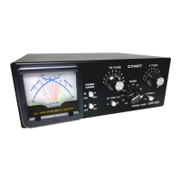
Rating
Frequency range : 1.8 – 60MHz Band : 11 bands
Input impedance : 50Ω Output impedance : 10 – 600Ω
Tolerable transit power : 300W or lower (SSB) Minimum SWR measurement power : 6W or higher
Lighting power supply : DC11V – 15V, Approx. 250mA
Dimensions : 250 (W) x 93 (98) (H) x 200 (242) (D) Weight : Approx. 2.7Kg
Connection procedures
CAT-300 shall be connected between the radio and the antenna or among the radio, the SWR meter and the
antenna using a 50Ω coaxial cable of type 3D2V, 5D2V and so forth.
If the antenna is a long wire type, connect via [ANT2] (terminal). Connect the ground wire to [GND]
(terminal).
Operation procedures
To use CAT-300 exclusively for reception such as BCL, press and turn [ON] the TUNER switch to
enable tuning operation. Then adjust the [BAND] switch, TR TUNE and X TUNE so that the S
meter of the receiver or the reception signal level is maximized. Use the tuning table below for reference.
To use CAT-300 for transmission, operate according to the procedures below:
1. Set the ANTENNA switch to the [ANT1] or [ANT2] of the connector connecting to the antenna.
Set to [ANT2] when a long wire antenna is connected to the terminal.
2. Lower the power control for the transmitter completely (set the transmitter power to 10W or lower).
3. Set the [BAND] switch to the transmission frequency band and set the TR TUNEandX TUNE
scales to the values specified in the tuning table below:
Tuning table
Frequency (MHz) BAND TR TUNE X TUNE
1.8MHz 1.8MHz 5.4 3.6
1.9MHz 1.9MHz 4.9 3.2
3.5MHz 3.5MHz 4.4 3.0
3.8MHz 3.8MHz 3.7 2.5
7MHz 7MHz 2.8 2.0
10MHz 10MHz 2.0 1.3
14MHz 14MHz 1.5 1.0
18MHz 18MHz 9.5 9.6
21MHz 21MHz 7.0 6.3
24MHz 24/28MHz 5.0 4.1
28MHz 24/28MHz 4.8 3.3
50MHz 50MHz 1.5 1.2
Note: This is the data for input impedance 50Ω load. These values are strictly for reference.
4. Input the transmission power until the needle of the reflection power meter of the connected SWR meter
deflects with CW, AM or FM modulation.
5. Turn the TR TUNE dial while transmitting to match the point where meter deflection is minimized.
6. Then turn the X TUNE dial to match the point where meter deflection is smaller than the degree in
previous Section 4.
7. Repeat the procedures 4 – 5 to find the point where the meter jumping(deflecting?) is minimized. This
point is the turning point (best SWR value)
8. If low SWR cannot be obtained, stop transmission immediately and set the [BAND] switch one step lower
to resume the tuning operation again from previous Section 4.
9. Operation at the maximum transmission output 300W is possible when a low SWR is obtained.
Comet Co., LTD 4-18-2 Tsuji, Minami-ku, Saitama City, Saitama 336-0026
TEL: 048-839-3131 FAX: 048-839-3136
URL: http://www.comet-ant.co.jp
Product appearance and specifications are subject to change
without notice for improvement of the product.

 Loading...