Do you have a question about the Comet CFM-95SL and is the answer not in the manual?
Adjust element length based on target frequency for optimal SWR, referencing the provided tuning chart.
Connect the assembled upper and lower antenna elements to the power feeding coil.
Secure the three antenna radials to the power feeding coil, ensuring they are tightened with nuts.
Mount the two brackets onto the support pipe, pass coax through, and connect to the SO-239 connector.
Slide the power feeding coil assembly into the mounting pipe and secure it with the hex bolt.
Follow all safety instructions, use non-conductive tools, and work with an assistant for outdoor installations.
Maintain a safe distance from power lines; assume all overhead lines are live to prevent contact.
Guidelines for assisting someone in contact with electricity, emphasizing not to touch the person directly.
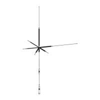
The CFM-95SL is a 5/8 wave LPFM broadcast base station antenna designed for outdoor installations. This antenna is engineered to provide reliable performance for low-power FM broadcasting applications. Its design focuses on ease of assembly and tuning, making it suitable for users who need to set up a broadcast antenna efficiently.
The primary function of the CFM-95SL antenna is to transmit FM signals within the 88-108MHz frequency range. It is built to handle a maximum power input of 200 Watts, making it suitable for various LPFM broadcasting setups. The antenna's design emphasizes achieving a good signal-to-noise ratio (SWR) for optimal transmission quality.
For usage, the CFM-95SL requires careful assembly and tuning to ensure proper operation. The assembly process involves attaching the upper and lower elements, connecting them to the power feeding coil, and then securing the three radials to the power feeding coil. The power feeding coil itself is designed to be slid into a mounting pipe and secured with a hex bolt. The antenna is intended to be mounted on a support pipe, and the coax cable should be passed through this pipe and connected to the SO-239 connector on the power feeding coil. The antenna's weight and required mast size (1 to 2.5 inches) should be considered during installation to ensure stability and safety.
A key usage feature of the CFM-95SL is its tunability. The antenna comes with a tuning chart that allows users to adjust the length of the upper element based on their desired transmit frequency. This adjustment is crucial for optimizing the antenna's performance and achieving an acceptable SWR. The manual notes that precise measurement of the upper element is not strictly necessary; being within 1/2 inch of the target length should result in acceptable SWR levels. This flexibility simplifies the tuning process for users.
The antenna's design includes components like a power feeding coil, mounting pipe, mount brackets, U-bolts with lock washers and nuts, hex bolts, hex bolts with lock washers, upper and lower elements, a hose clamp, radials with nuts, and screws with star washers. These components are designed for straightforward assembly, allowing users to set up the antenna without specialized tools beyond basic wrenches.
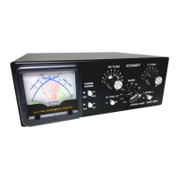
For maintenance and optimal performance, the manual emphasizes the importance of using high-quality 50 Ohm impedance coax cable. This is crucial for maintaining the antenna's high gain and ensuring efficient signal transmission. The tuning chart provided with the antenna is also a valuable maintenance feature, as it allows users to re-tune the antenna if their broadcast frequency changes or if performance needs to be re-optimized over time. After initial setup or re-tuning, it is recommended to check the system's SWR to ensure it is less than 1.5:1 before transmitting, which is a key indicator of good antenna health and performance.
Safety is a paramount consideration for outdoor installations of the CFM-95SL. The manual provides extensive safety information, including warnings about contacting power lines, the importance of working with an assistant, and using non-conductive tools and ladders. It stresses the need to survey the installation area for overhead power lines and to assume all overhead lines are live. In case of contact with a power line, users are instructed to leave the equipment and call the power company. The manual also advises against installing the antenna during foul weather. Proper grounding of towers and masts, along with the use of lightning arrestors for cables, is recommended to prevent electrical and fire damage, as well as injury from lightning strikes or static build-up. These safety guidelines are critical for the long-term maintenance and safe operation of the antenna system.
In summary, the CFM-95SL is a user-friendly LPFM broadcast antenna designed for efficient signal transmission. Its features include a straightforward assembly process, a tuning mechanism for frequency optimization, and clear guidelines for safe installation and maintenance, all aimed at providing a reliable broadcasting solution.
| Type | Mobile |
|---|---|
| Impedance | 50 Ohms |
| VSWR | 1.5:1 |
| Connector | UHF |
| Length | 96 inches |
| Connector Type | SO-239 |