CAT-300
Thank you very much for purchasing our product.
Although our products have been manufactured under strict quality control, please contact the stores where
you purchased them as soon as possible if you find troubles such as damages caused by an accident during
transport.
To deliver the performance of CAT-300 fully, please read this instruction manual through so that you can use
this product correctly for a long period.
Features
- CAT-300 is an antenna tuner capable of inputting transmission power up to 300W and it can be used to
tune to dipole, vertical, automotive whip, long wire and other various types of antenna in all bands
between 1.8MHz and 60MHz.
- The meter adopts the cross method and is capable of measuring the traveling wave, the reflected wave and
SWR value concurrently.
- The meter scale board is equipped with a lamp and makes it esier to read by lighting the lamp at night
(when an external power is connected).
Precautions for use
- Although CAT-300 is designed to sufficiently endure 300W input, please set up the transmission output
during tuning to 10W or lower to protect the transmitter since extremely high voltage may occur in the
tuning circuit and the impedance seen from the transmitter may fluctuate dramatically.
- Do not operate the BAND switch while the transmitter is transmitting. It may temporarily increase the
load SWR to infinite size and cause failure in the transmitter or CAT-300. Furthermore, do not apply
transmission power of 300W or larger on CAT-300. to avoid a failure. Failure to observe this precaution
may result in malfunction
- Although CAT-300 is capable of tuning in the range of 10Ω – 600Ω (SWR approximately 2.5 : 1),
adjust the antenna system instead of turning by force when the SWR for the connected antenna system is
outside the range.
- Never apply 15V or higher as the external power supply voltage for meter scale board lamp to avoid a
failure. Failure to observe this precaution may result in malfunction.
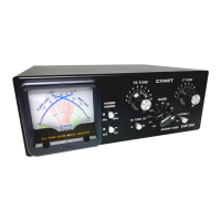
Parts names and descriptions
(1) Indication meter (8) ANTENNA switch
This meter indicates the FWD (traveling wave), This is the switch to select ANT1 or ANT2.
REF (reflected wave) and SWR. (9) ANT.2 (M- type connector)
(2) Measurement range switching button Connects an antenna, dummy load, and so forth.
This is the button to switch the maximum value (10) ANT.1 (M- type connector)
for FWD (traveling wave) power indication. Connects an antenna, dummy load and so forth.
(3) TR TUNE (11) Power input terminal
A variable capacitor that changes the impedance on Terminal for external power input for the meter lighting.
the input side (transmitter side). (12) ANT.2 (Terminal)
(4) X TUNE Connects a long wire antenna and so forth.
A variable capacitor that changes the impedance It cannot be used simultaneously with ANT2
on the output side (antenna side). Connector. To use the terminal, do not connect
(5) AVG/PEP switch any antenna, etc. to the ANT2 connector.
Indicates the average power when it is set to AVG (13) INPUT (M-type connector)
and the PEP monitor when set to PEP during This is the connector to connect the radio output.
power measurement. (14) GND
(6) TUNER switch Use this to connect the ground wire.
Tuning operation can be executed by turning this switch TVI and BCI can be reduced by connecting this terminal
ON and turning operation cannot be executed but it to the GND terminal for the radio and grounding this
works as a SWR meter by turning it OFF. terminal.
(7) BAND switch
This is the switch to select the 1.8MHz – 50MHz band.