SelectorSwitches
Inorderforthisthermostattocontrolyoursystem,thesystemtypemustbespecified
by the selectorswitches onthe printedcircuit boardinside the thermostat. Thereis
alsoaselectorswitchforyourchoiceofFahrenheitorCelsiustemperaturedisplay.
ŸF˚/C˚selector(Fahrenheit/Celsius)
Your thermostatis setfor F˚mode fromthe factory.Inorder tochangeto C˚mode,
slidetheswitchtoC˚andMovethebatteryoutandwaitforabout1minutethenplace
thebatteries..
NOTE: Unless press any key about 2 seconds without the battery, then place the
battery again. the thermostat will not change temperature mode. All programs and
settingswillbelost.
ŸHeatingSystemSelector(HG–HEswitch)
Thefactorypositionforthisswitchisinthe“HG”position.Leaveinthispositionifyou
haveagasfurnaceoranoilburner.Ifyouhaveanelectricfurnace,testtoseewhether
theHeatandFancomeonasexpectedafterinstallation.IftheFanoperationisnormal,
leave it in the “HG” position. If the Fan does not come on within a minute of the
thermostatcallingforheating,changetheswitchpositionto“HE”.Thesystemselector
hasnoeffectinthecoolingmode.
NOTE: “HG”position isfor gasand most other systems.“HE”positionisfor certain
electricsystemshavingafanrelay.
ŸSystemSelector(STANDARD–HEATPUMPswitch)
ThefactorypositionforthisswitchisintheSTDposition.Leaveitinthispositionifyou
have ANY system that uses gas, oil, electric, or hot water heating. If you have a
singlestageHeatPump(noauxiliaryoremergencyheatsource),thenslidetheswitch
totheHPposition.Besurethereversingvalvewireisconnectedtothecorrectterminal
foryourheatpump(Y/O)or(W/B).
ŸAutoRecoveryselector(DISABLE/ENABLE)
YourthermostatissetfromthefactorywiththeAutoRecoveryFeatureenabled,which
complieswiththeEPAENERGYSTARProgram.IFyouprefertousenormalrecovery,
slidetheswitchtotheDISABLEposition.
INSTALLATION
WhatYouNeed
Thisthermostatincludestwo#8slottedscrewsandtwowallanchorsformounting.To
installyourthermostat,youshouldhavethefollowingtoolsandmaterials.
ŸSlottedScrewdriver(s)
ŸSmallPhilipsscrewdriver
ŸHammer..
ŸElectricdrilland3/16”bit
ŸTwo1.5V(AA)sizealkalinebatteries(included)
RemoveOldThermostat
CAUTION:Donotremoveanywiringfromexistingthermostatbeforereadingthe
instructionscarefully.Wiresmustbelabeledpriortoremoval.
INPORTANT!Turnoffthepowertothefurnaceatthemainpowerpaneloratthe
furnace.
Removeexisting thermostatcover andthermostat.See Figure 1. Somethermostats
willhave screws or otherlocking devicesthatmust first beremoved. Oncethe wall
mounting plate is exposed, look for wires. If wires are not visible, they may be
connectedtothebackofthewallplate.Again,lookforscrews,tabs,etc.Somemodels
havedoorsthatopentoexposewiresandmountingscrews.SeeFigure1.
TypicalHomeThermostats
Figure1
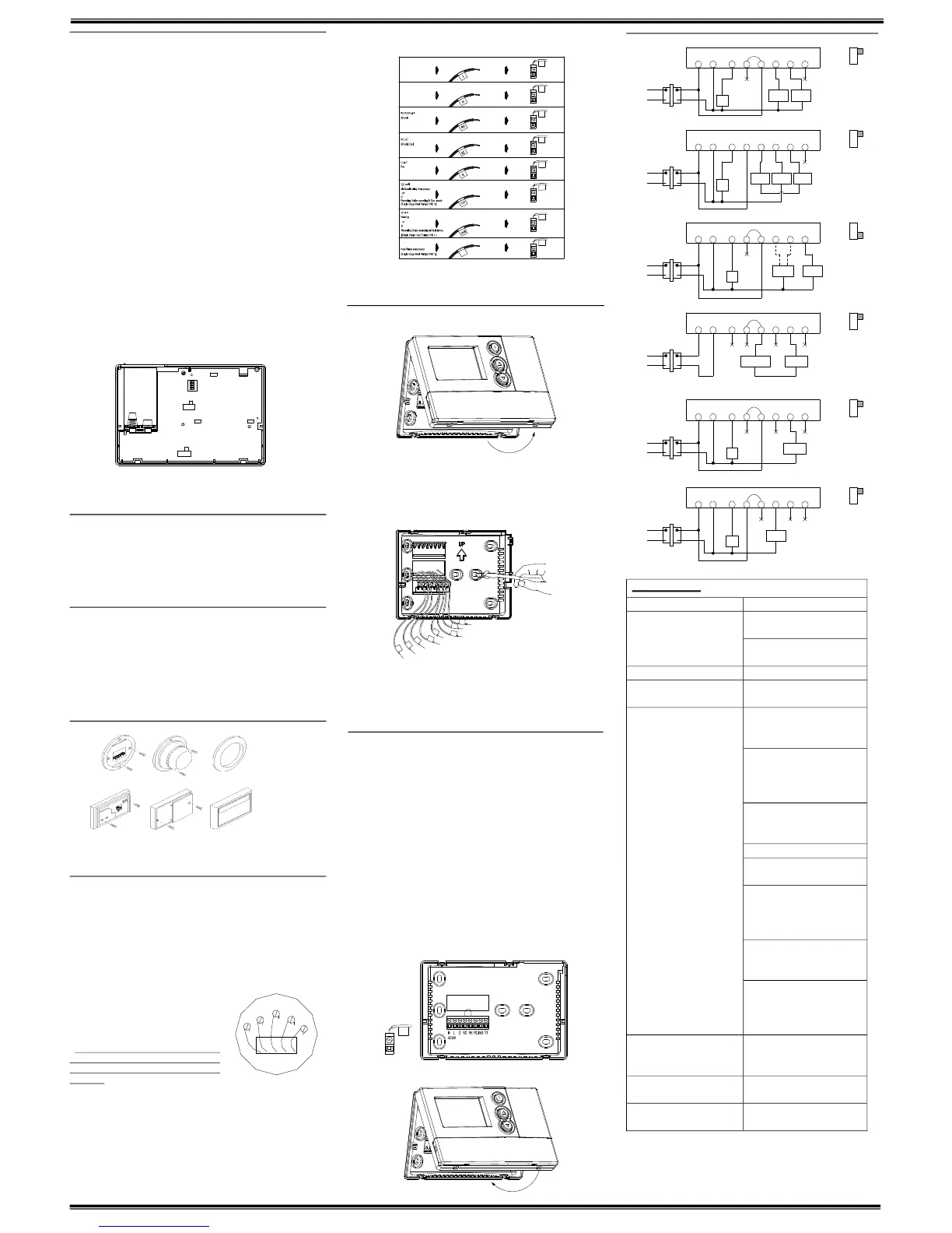
WiringLabeling
ŸEach wirecomingfrom the wall tothe existing thermostat is connectedtoterminal
pointonthatthermostat.Eachof theseterminal points is usuallymarkedwithacode
letterasshowninTableAbelow.
ŸNotethatthisthermostathasmultiplefunctionterminalsthatallowSingleStageHeat
Pumpcapability. Standard systems use:Rh, Rc,G, Y,W.[SingleStageHeat Pumps
use:R,Y,G,andOorB.]TableAbelowshowsthemultiplefunctionsoftheterminals.
Usetheterminalsthatmatchyoursystem.
ŸThenumberofwiresinyoursystemcanbeasfewastwo(forheatonlysystems),as
many as eight, or any number in between. If you follow the labeling procedures
correctly,youdonothavetobeconcernedabouthowmanywiresthereare.
ŸThereisoftennoterminalmarkingontheexisting
thermostat of two wire, heat only systems. Just
connecteitherofthewirestotheRHterminal,then
connect the other wire to the W terminal to
completethecircuit.
ŸIMPORTANT!BEFOREDISCONNECTINGANY
WIRES, APPLY THE SELFADHESIVE LABELS
PROVIDEDTOTHEWIREASSHOWNINTABLE
ABELOW.(Forexample,attachthelabelmarked
Wtothe wirethattoestotheWorHterminalonyourexistingthermostat.)IGNORE
THECOLOROFTHEWIRESsincethesedonotalwayscomplywiththestandard.
ŸAfterlabelingwires,disconnectthemfromtheexistingthermostat.
ŸRemoveexistingwallplate.Tomakesurewiresdonotfallbackintowallopening,you
maywanttotapethemtothewall.
ŸIfholeinwallislargerthannecessaryforwires,sealthisholewithinsulatingmaterial
sothatnohotorcold aircan entertheback of thethermostatfromthe wall.This air
couldcauseafalsethermostatreading.
TableA
Ifthecodeletteronyour
existing
Thermostatis
thenmarkthewirewith
labelshown
andconnectto
thermostatterminal
shown
NOTE: Donotconnecta “Common”wire(sometimes labeled“C”)to anyterminal on
this thermostat. Tape up the wire and do not use. This wire provides electricity to
nonbatterypoweredthermostats.
MountWallplateandThermostat
Ÿ Remove the wall plate from your thermostat by pressing the release tab on the
bottomofthethermostat.SeeFigure2.
Figure2.
ŸPositionwallplate onwallandpull existingwires throughlargeopening. Thenlevel
forappearance.Markholesfor plasticanchorsprovided,ifyourexistingholesdonot
lineupwiththoseonthewallplate.
ŸDrillholeswith3/16”bitandgentlytapanchorsintothebolesuntilflushwithwall.
Ÿ Reposition wallplate to wall, pulling wires through large opening. Insert mounting
screwsprovidedintowallanchorandtighten.SeeFigure3.
Figure3.
NOTE:5WireSystems
IfyourthermostathasonewiremarkedRorRh(2,3,or4wiresystem),thenleavethe
jumperwirebetweentheRhandRcterminalsonthewallplate.Otherwise,ifyouhave
separateRhandRcwires(5wiresystem),thenremovethejumperwirebetweenthe
RhandRcterminals.
ConnectWiresandMountThermostattoWallplate
ŸMatchandconnectthelabeledwirestotheappropriatecodedterminalscrewsonthe
wallplate.(See Figure4,5.)Ignoreany wireswhichmay bepresent,butwhichwere
noteconnectedtotheoldthermostat.
ŸRefertotheWiringDiagramsbelowtobesureyoursystemiswiredcorrectly.
ŸIfyoursystemisasinglestageheatpumpandusesanOorBwire,youmustmove
the System Selectorswitch inside thethermostat to theHeat Pump position. Ifyou
havea normal furnace orelectric system,leave theswitchin theStandard position.
RefertotheSystemSelectorsectiononthebackformoreinformationonthisswitch.
ŸBesuretotightentheterminalscrewssecurely,otherwisealoosewirecouldcause
operationalproblemswithyoursystemorthermostat.
Ÿ Push excess wires back into the hole to prevent interference when installing the
thermostattothewallplate.
ŸMakesuretheSystemSwitchissettoOFF,andtheFanSwitchissettoAUTO.
Ÿ Insert the bottom tabs on thethermostat body into theslots atthe bottom of the
wallplate.Press thetop ofthe thermostatbodyto snapit intothe wallplate.Referto
Figure6.
NOTE: Do not forcethe thermostat ontothe wallplate, as thet erminal pins maybe
damaged.Ifitdoesnotsnapproperly,thethermostatmaynotwork.
Ÿ Insert thetwoAA sizealkaline batteries, observing the polarity marked insidethe
batterycompartment.
ŸSwitchonthemainpoweratthepanelorfurnace.
Figure4 Figure5
Figure6
WiringDiagrams
TROUBLESHOOTING
Problem Solution
1. Check battery connections and
batteries.
NoDisplay
2. Move the battery out andwait for
about1minute
EntireDisplayDims. 1.ReplaceBatteries.
Auto Fan Does Not Turn On
Properly.
1. Move HG/HE selector to correct
position.
1.Checkthatthefunctionswitchisin
the correct position (“HEAT” or
“COOL”).
2.Theremaybeasmuchas4mintue
delaybeforethesystemturnsOn–
wait and check. (Compressor
protectiondelay.)
3. Check your circuit breakers and
switchestoensurethere is power
tothesystem.
4.Replacebatteries.
5. Make sure your furnace blower
doorisclosedproperly.
6.Ifyournonheatpumpsystemonly
uses 4wires, be sure the jumper
wire is installed between the Rh/B
andRc/Oterminals.
7. Check the position of the
Reversing Valve selector switch:
StandardorHeatPump.
Heating or Cooling Does Not Go
OnorOff.
8. If you have singlestage heat
pump, be sure the jumper wire is
installed between the Y and W
terminals.
ErraticDisplay 1.Movethe batteryout holdanykey
thenplacethe batteryagain. Then
reprogram.
If unit continues to operate in the
Offposition.
1.Replaceunit.
Thermostat permanently reads
“HI”,“LO”,or“E1”,“E2”..
1.Replaceunit.
Ifyouexperienceanyotherproblems,callusfortechnicalassistance.
Theservicenumberis18665919898
W
G
Y
RH
RC
WallmountingPlate Thermostat Cover
WallmountingPlate Thermostat Cover
1 2 3 4
RECO VER YEN ABLE
DISA BLE
STD HP
HG HE
K6
JP1
K5
CENTI GRAD E FAH REN HEIT
Y1
Y1
RH
RC
G
Y/ O
W/B
Y1
AC2 4V
AC2 4V
N
L
N
L
Y/O
Rh
Rc
G
L
N
Y1
W/B
RH
G
Rc Rh
Y/O
W/B Y1
Wallplate
Terminals
Jumper
Fan
Relay
Cool
Contactor
HeatRelay
orValve
System
Selector
STD
HP
Fan
Relay
Compressor
Contactor
Reversing
Valve
Wallplate
Terminals
System
Selector
HP
STD
Wallplate
Terminals
No
Jumper
System
Selector
HP
STD
Jumper
Heat
Mode
Cool
Mode
OR
Heat24Vor
MillivoltSupply
HeatRelay
orValve
Wallplate
Terminals
Jumper
System
Selector
HP
STD
Wallplate
Terminals
System
Selector
HeatRelay
orValve
Jumper
HP
STD
Fan
Relay
Fan
Relay
Wallplate
Terminals
Cool
Contactor
System
Selector
HP
STD
Jumper
4WireHeat/CoolSystem
5WireHeat/CoolSystem
SingleStageHeatPumpSystem
2WireHeatOnlySystem
3WireHeatOnlySystem
3WireCoolOnlySystem
G
Rc
Rh
Y/O
W/B Y1
Fan
Relay
Heat
24V
Supply
Cool
Contactor
Heat
Relay
orValve
G
Rc Rh
Y/O
W/B
Y1
G Rc Rh
Y/O
W/B Y1
G Rc Rh
Y/O
W/B Y1
G Rc
Rh
Y/O
W/B Y1
120V
AC
120V
AC
120V
AC
120V
AC
120V
AC
120V
AC
N
L
AC24V
NL
AC
24V
NL
AC24V
N
L
AC24V
NL
AC24V
NL
AC24V
 Loading...