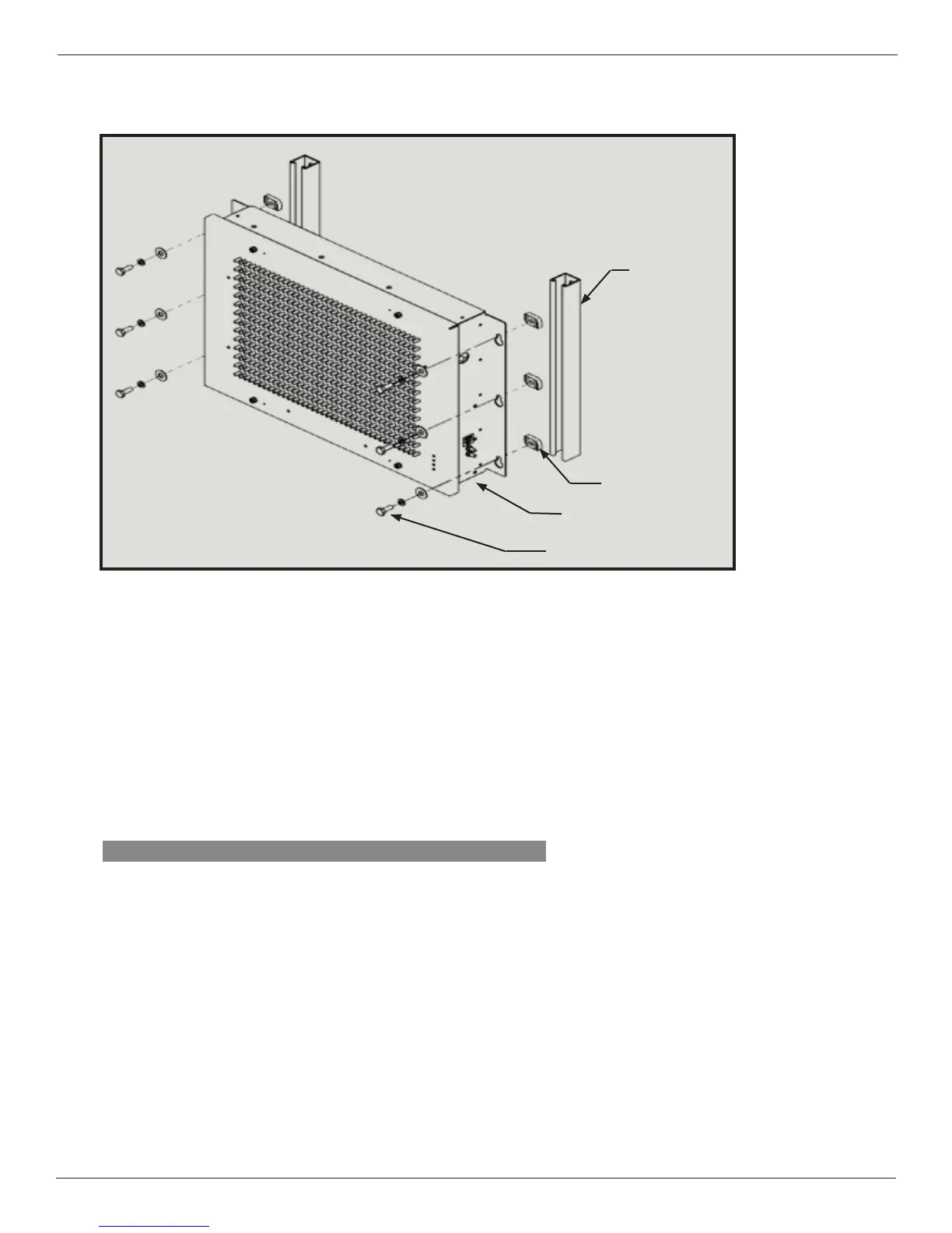
Figure 1. Wall mount illustration with unistrut
C.5 Damper Controller Connection
Step 1. Loosen the four captive thumbscrews and remove the front panel of the Return Air Damper unit.
Step 2. See wiring diagram to what scheme is ideal.
RETURN DAMPER ASSEMBLY UNIT
MOUNTING HARDWARE
UNITSTRUT
SPRING NUT
PAGE 2 H2 ZERO: VRLA BATTERY ROOM HYDROGEN VENTILATION SYSTEM
8p POWER/CONTROL INPUT (J3)
C.6 Power and Control Connection
PIN 1 PIN 2 PIN 3 PIN 4 PIN 5 PIN 6 PIN 7 PIN 8
RUN IN OPEN FAULT IN GRND TXD RXD PWR + PWR -
Jumper J3 is used to connect between H2 Zero Main Controller using the 8p position connector.
See “Figure 2. Scheme 2 Wiring Diagram” on page 4
INSTALLATION & OPERATIONAL MANUAL