SOLAR PUMPING INVERTER I USER MANUAL
15
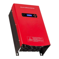
Number Description Parameters
1 Keyboard Esc, Up, Down, On/O
2 LCD Screen Display with Cover
12*64px
16*4 Characters
3 LED Indicator Light
Power, Run/Stop, Error
Note: Run/Stop LED Indicator Light
Flashing: Inverter is working on
O: Inverter stop by On/ button
On: Inverter shutdown for the other
reasons
4 Mounting holes 4 screws
5 AC Input
1 Phase Input: L+N+ Ground
3 Phase Input: R+S+T+ Ground
6 Solar Input Positive(+) and Negative(-)
7 AC Output U+V+W
8 Communication RS232
9 Well/Borehole Sensor 2 Pins
10 Tank Sensor 3 Pins
11 Socket for motherboard Connect to motherboard
12 Socket for Display board Connect to Display board
AC Input/Output
Do not connect the breaker between inverter AC output connector with the pump.
AC Output to 3 Phase Pump Connection:
Red Colour Yellow Colour Blue Colour Yellow_Green
Pump-U Phase Pump-V Phase Pump-W Phase Ground/Earth
Note: If the pump water flow is minimal, please try to change any 2 wire of 3 phase
and change the forward or reverse running direction.
AC Output to Single Phase Pump Connection:
Please refer to the 17-19.
AC Input connection:
AC Input to Solar Pumping Inverter
Red Colour Yellow Colour Blue Colour Yellow_Green
AC-U Phase AC-V Phase AC-W Phase Ground/Earth
 Loading...