EasyManua.ls Logo

Commodore Plus 4 - Page 435

Commodore Plus 4
464 pages
Print Icon
To Next Page IconTo Next Page
To Previous Page IconTo Previous Page
Loading...
Appendix
G
Plus/4
Memory
Maps
Three
different
maps
are
presented.
The
first
describes
each
of
the
registers
of
the
graphics
chip.
The
second
gives
an
overview
of
the
Plus/4's
memory
usage.
The
third
gives
as
much
detail
as
possible
about
each
location
in
the
Plus/4.
Graphics
Chip
Register
Map
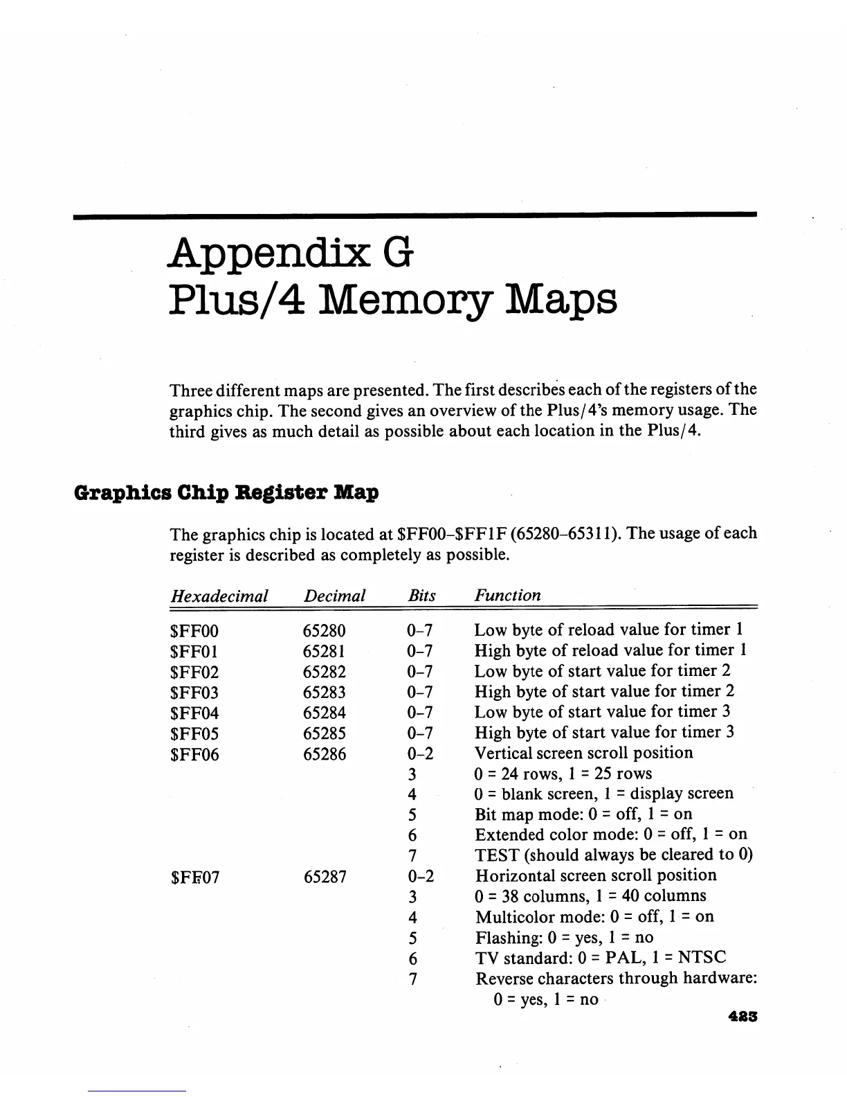
The
graphics
chip
is
located
at
$FFOO-$FF1F
(65280-65311).
The
usage
of
each
register
is
described
as
completely
as
possible.
Hexadecimal
$FF00
$FF01
$FF02
$FF03
$FF04
SFF05
$FF06
$FF07
Decimal
65280
65281
65282
65283
65284
65285
65286
65287
Bits
0-7
0-7
0-7
0-7
0-7
0-7
0-2
3
4
5
6
7
0-2
3
4
5
6
7
Function
Low
byte
of
reload
value
for
timer
1
High
byte
of
reload
value
for
timer
1
Low
byte
of
start
value
for
timer
2
High
byte
of
start
value
for
timer
2
Low
byte
of
start
value
for
timer
3
High
byte
of
start
value
for
timer
3
Vertical
screen
scroll
position
0
=
24
rows,
1
=
25
rows
0
=
blank
screen,
1
=
display
screen
Bit
map
mode:
0
=
off,
1
=
on
Extended
color
mode:
0
=
off,
1
=
on
TEST
(should
always
be
cleared
to
0)
Horizontal
screen
scroll
position
0
=
38
columns,
1
=
40
columns
Multicolor
mode:
0
=
off,
1
=
on
Flashing:
0
=
yes,
1
=
no
TV
standard:
0 =
PAL,
1
=
NTSC
Reverse
characters
through
hardware:
0
=
yes,
1
=
no
483