CHAPTER
Introducing the
VIC
20
Computer
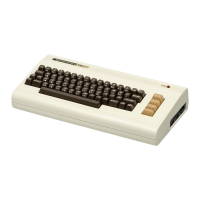
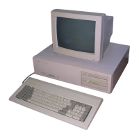
When
you first unpack the VIC 20, you will find the equipment
'shown in Figure
1-1:
· The VIC
20
computer
• Television
RF
modulator (small black box)
• Power supply (larger plastic box)
·
TV
switch box
· Video cable
While your system may include additional components, all systems
include this basic equipment. This chapter identifies each component and
connector provided by Commodore and introduces the function of each.
Place the VIC
20
on a flat surface such as a table. Make sure that you
have room
to
put a television near the VIC 20, ideally directly behind it.
REAR
AND
SIDE
PANEL
All
of
the switches, connectors, and interfaces are located
at
the side
and back
ofthe
VIC
20
computer. These components are labeled in Figure
1-2.
It
is important
that
you learn the function and location
of
each
1