Chapter
1.
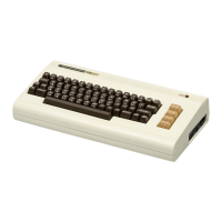
Introducing the
VIC
20
Computer 3
When you turn the power switch ON, the VIC will display a
dark
screen
for a short time. During this period it
is
initializing itself;
that
is, it
is
checking
out
its internal systems
and
determining how much memory it has
available.
When you
turn
the power
OFF,
all programs and data in memory that
were
not
stored onto either diskette
or
tape will be lost.
Power
Connector
The power supply has two cables attached to it. One plugs into any
standard
110
volt AC outlet. The other plugs directly into the power
connector next to the
ON/OFF
switch on the side
ofthe
VIC
20.
Game
Port
This connector is used for the various game controllers available for
the VIC 20, as well as for the light pen and some special application devices.
AT ARIjoysticks and paddles will work with this port, as well as those made
by Commodore.
Parallel
User
Port
The parallel user
port
is
a connector that allows you to hook up devices
(such as the VIC modem) to the VIC
20.
More advanced users may use this connector for custom applications
as well, since the signals coming from it can be programmed directly by the
VIC
20.
cassette Interface
The cassette interface
is
used to connect the Datassette, which
is
a
special digital tape recorder. You can use it to store
and
reload programs
and
data
into the VIC 20. The Datassette
is
described later in this chapter.
Serial
Port
The serial
port
is
used to connect the computer
to
the model
1515
printer, the disk drive,
and
other devices using a serial
input/
output