160
The
VIC
20
User
Guide
There is also a Fire button, which has its own switch. Using the method
described in the following sections, your program can tell whether these
switches are open
or
closed
and
thus determine which way the joystick
is
pointing.
By
moving the joystick, you can direct elements
on
the screen.
The
VIA
Chips
The joystick
is
connected to the VIC through integrated circuits called
Versatile Interface Adapters (VIAs). Certain pins
of
the VIA chip connect to
the "outside world." These pins receive a signal sent to them (input)
or
send a
signal
out
to
another device (output). Circuitry in the VIA chip enables the
VIC to set
or
examine the signals
on
these pins using memory locations. The
signals can be read
and
controlled through PEEKs
and
POKEs in BASIC.
Testing
the
Joystick
SWItches
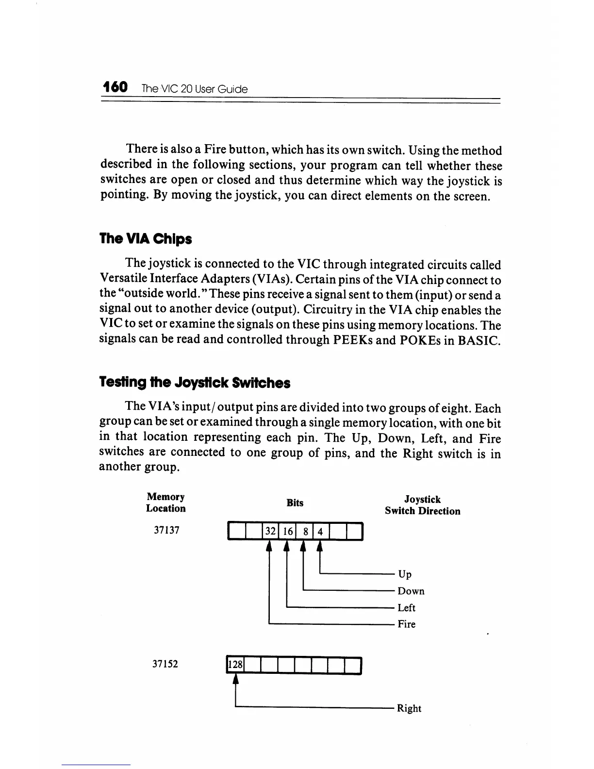
The VIA's
input/
output pins are divided into two groups
of
eight. Each
group can be set
or
examined through a single memory location, with one bit
in
that
location representing each pin. The Up, Down, Left,
and
Fire
switches are connected to one group
of
pins, and the Right switch
is
in
another group.
Memory
Location
37137
37152
Bits
I 1
1321161
814
1
•
I
1 I
Joystick
Switch Direction
Up
Down
Left
Fire
fl-
__________
Right