164
The
VIC
20
User
Guide
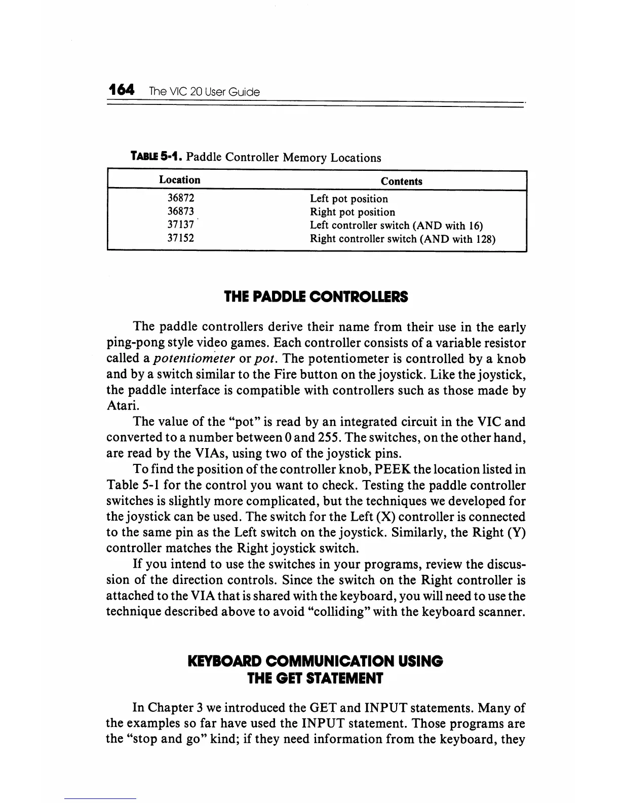
TABLE
5·1.
Paddle
Controller
Memory
Locations
Location
36872
36873
37137
37152
Contents
Left
pot
position
Right
pot
position
Left controller switch (AND with
16)
Right controller switch (AND with 128)
THE
PADDLE
CONTROWRS
The paddle controllers derive their name from their use in the early
ping-pong style video games. Each controller consists
of
a variable resistor
called a
potentiometer or pot. The potentiometer
is
controlled by a knob
and by a switch similar to the Fire button on the joystick. Like the joystick,
the paddle interface
is
compatible with controllers such as those made by
Atari.
The value
of
the
"pot"
is
read by
an
integrated circuit in the VIC and
converted
to
a number between 0 and 255. The switches, on the other hand,
are read by the VIAs, using two of the joystick pins.
To find the position
ofthe
controller knob,
PEEK
the location listed in
Table
5-1
for the control you want to check. Testing the paddle controller
switches
is
slightly more complicated,
but
the techniques
we
developed for
the joystick can be used. The switch for the Left (X) controller
is
connected
to the same pin as the Left switch on the joystick. Similarly, the Right (Y)
controller matches the Right joystick switch.
If
you intend to use the switches in your programs, review the discus-
sion
of
the direction controls. Since the switch on the Right controller is
attached to the VIA that
is
shared with the keyboard, you will need to use the
technique described above to avoid "colliding" with the keyboard scanner.
KEYBOARD
COMMUNICATION
USING
THE
GET
STATEMENT
In Chapter 3
we
introduced the GET and
INPUT
statements. Many
of
the examples so far have used the
INPUT
statement. Those programs are
the "stop and go" kind; if they need information from the keyboard, they