302
The
VIC
20
User
Guide
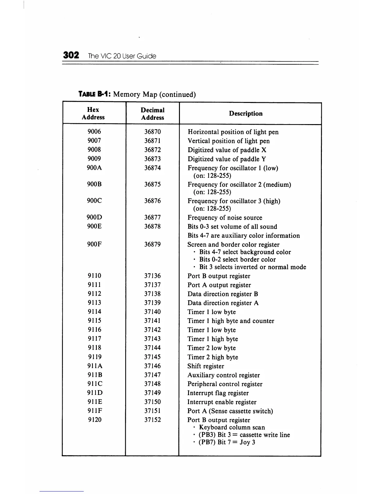
TABLE
B-1:
Memory Map (continued)
Hex
Decimal
Description
Address
Address
9006
36870
Horizontal position of light pen
9007
36871
Vertical position
of
light pen
9008
36872
Digitized value
of
paddle X
9009
36873 Digitized value
of
paddle Y
900A
36874
Frequency for oscillator 1 (low)
(on: 128-255)
900B
36875
Frequency for oscillator 2 (medium)
(on: 128-255)
900C 36876 Frequency for oscillator 3 (high)
(on: 128-255)
900D
36877 Frequency
of
noise source
900E
36878
Bits 0-3 set volume
of
all sound
Bits 4-7 are auxiliary color information
900F 36879 Screen and border color register
Bits 4-7 select background color
• Bits 0-2 select border color
. Bit 3 selects inverted
or
normal mode
9110 37136
Port
B output register
9111
37137
Port A output register
9112 37138
Data
direction register B
9113
37139
Data
direction register A
9114
37140 Timer I low byte
9115
37141
Timer I high byte and counter
9116 37142 Timer I low byte
9117 37143 Timer I high byte
9118 37144 Timer 2 low byte
9119 37145 Timer 2 high byte
911A 37146 Shift register
911B 37147
Auxiliary control register
911C
37148
Peripheral control register
911D 37149 Interrupt flag register
911E 37150 Interrupt enable register
911F
37151
Port
A (Sense cassette switch)
9120 37152
Port
B output register
Keyboard column scan
(PB3) Bit 3
= cassette write line
(PB7) Bit 7
=
Joy
3