EasyManua.ls Logo

Commodore VZ User Manual

Commodore VZ
18 pages
To Next Page IconTo Next Page
Page #1 background imageLoading...
Page #1 background image
Page 1
Copyright © 2005 - ASR Electronics. All rights reserved.
VY-VZ Commodore
Blaupunkt audio system
Low-level output conversion / Auxiliary Input
Installation Instructions
Introduction:
The procedures outlined in this document are intended as a guide to assist in the installation and
modification to allow buffered line level outputs and/or Auxiliary Input. There are people of many different
skill levels out there, and the instructions have been formulated to cater to many different levels. Whilst
something may seem mundane and obvious to you, it may not be to everyone. I do encourage reading
through the procedure entirely and to clear up any points of uncertainty before commencing.
The job entails the mounting of one or two small PCBs (Printed Circuit Board) and attachment of an
additional socket inside the head unit, and the cutting of a small slot into the cradle metalwork to facilitate
mounting of the pins which mate with the socket. The kit consists of a small PCB containing the buffer
components, the additional socket, a lead-out cable assembly terminated with gold RCA sockets and a
bullet connector, a guide template to assist with the positioning of the slot which is to be cut into the cradle
metalwork, some various internal hook-up wires, nylon standoffs to support the board(s) once installed, and
a length of 0.5mm solder. On completion of the modification and re-fitting the unit to the vehicle, there is
absolutely no visible evidence of any departure from factory stock – nobody will know until you turn up the
volume control.
The operation of the internal amplifiers remains unaffected, so if the time comes to move the car onward but
you’d rather hold on to the “external” components of your system, the standard connections can be restored
to the door speakers, and the unit will continue to function as it always had.
The work involved does require some moderate soldering skills, and a generally handy nature with hand
tools. Do not underestimate the potential for damage to occur – there are several connections that need to
be soldered to the base unit PCB, which is heavily populated with “Surface Mount” components. As a
general guide, if you’ve ever fitted a “mod chip” to a Playstation (or especially a PS2!) you will have little or
no trouble with this aspect.
Question and Answer IconNeed help?

Do you have a question about the Commodore VZ and is the answer not in the manual?

Commodore VZ Specifications

General IconGeneral
BrandCommodore
ModelVZ
CategoryStereo System
LanguageEnglish

Summary

Introduction to Installation

Preparation and Tools

Essential Tools and Materials

Lists necessary tools like screwdrivers, Torx drivers, files, rotary tools, and adhesives.

Head Unit Removal and Disassembly

Removing the Head Unit

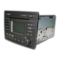
Step-by-step guide on how to extract the car's head unit using special tools.

Disassembling the Head Unit

Instructions for opening single-disc and six-stack head units to access internal components.

Vehicle Trim and Cradle Modification

Console and Dashboard Trim Removal

Guide to removing centre console and dashboard panels to access wiring and components.

Modifying the Head Unit Cradle

Step-by-step process for cutting a slot in the metal cradle using templates and tools.

Component Installation and Wiring

Attaching the Auxiliary Socket

Details on preparing surfaces and epoxying the auxiliary socket to the head unit connector.

Buffer Board Installation and Wiring

Mounting the buffer board, preparing connections, and wiring it to the base unit PCB.

Auxiliary Input PCB Installation and Wiring

Installing the input PCB, connecting signals, power, and telephone MUTE.

Mounting the 3.5mm Socket and Switch

Mounting the 3.5mm socket and activation switch in chosen locations and soldering connections.

Final Assembly and Testing

Finalizing Head Unit Connections

Inserting socket pins, checking connections, and applying strain relief to wiring.

Reassembling the Head Unit and Cradle

Reconnecting the head unit, refitting the facia, and checking cradle alignment.

Securing the Cradle and Testing

Fitting the lead-out assembly, securing the cradle, and final checks before powering up.

Related product manuals