82
5. Transport and installation on site
A A A
B B
A = B = 1,5 m
B
Use proper hoisting gears only such as
hoisting straps in compliance with DIN
standard 61360 with proper lifting ca-
pacity for connecting the load
suspension device (e.g. crane) and the
lifting device.
Only deploy load bearing equipment
which corresponds to the safety
instructions for lifting gear.
Use a transport harness compliant
with local regulations for transporting
by helicopter. The eyes provided may
not be used for this purpose (max.
acceleration if the eyes are used = 2 x g)
Never lift up or lash down the unit using
the shieldings!
Never relocate the machine if external
lines or hoses are connected to the
discharge valves, in order to avoid
damage to the valves and/or collecting
pipe and hoses.
When loading, the following points must be
observed:
* Secure the load suspension device or
the hoisting gear in the lifting device of
the screw compressor.
* When hoisting the compressor, set up
the hoisting gear in such a way that the
compressor, which must be set up
horizontally, is lifted vertically.
* Only relocate the compressor by itself.
* Raise and lower the compressor
carefully.
* After relocating, remove the load
suspension device or the hoisting gear
from the lifting device.
* Tie down the compressor on the cargo
area of the means of transport.
* Only tie it down at towbar and wheel
axles.
* When the chassis is being dismantled,
the shieldings with machine group may
only be supported under the base frame.
5.4 Installation on site
Fig. 10
Danger
The air intake must be positioned in
such a way that loose personal clothing
cannot be drawn in.
Make sure that the pressure pipe from
the compressor to the aftercooler or the
air system can expand as a result of
heat, and that it does not come into
contact with inflammable materials.
The air intake is to be designed in such
a way that no dangerous admixtures
(inflammable solvent vapors etc.,
but also other dangerous or toxic
substances) can be taken in. This also
applies to flying sparks.
Pipes and other parts with a surface
temperature of more than 80
°
C must be
suitably secured against contact and
suitably marked.
The operation of the compressor in
areas where there is a risk of explosion
is strictly forbidden! (Exception:
specially-made compressors with the
necessary technical modifications for
use in such areas)
Please also note the safety instructions
in Chapter 3 on the subject of
installation on site.
Location
The complete system is to be set up in
such a way that it is easily accessible and
that the required cooling is guaranteed.
Never block the air intake. Ensure that the
entering of moisture and dirt together with
the intake air is kept to a minimum.
The compressor is to be set up away
from walls.
Attention
The screw compressor is to be set up in
such a way that no air reflection can
take place, i.e. neither waste air nor
exhaust emissions may be drawn in; the
same applies to dangerous admixtures
to the air. Drawing this waste air in could
lead to overheating and a loss of power.
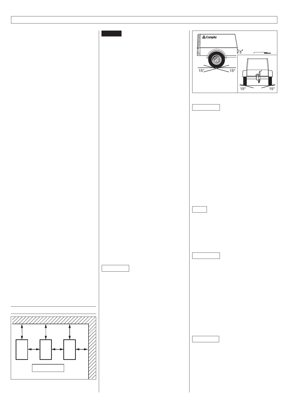
The compressor must be set up in as
horizontal a position as possible. Maximum
permissible inclination during operation:
* In direction of pull: 15 degrees
* Backwards: 15 degrees
* To the right and to the left: 15 degrees
Fig. 11
Attention
Greater inclinations endanger the
operating reliability of the screw
compressor.
When setting up the unit on ground that is
not horizontal, or with a variable angle (see
operating instructions) please consult
CompAir.
Set up the machine in such a way that
no inlets, outlets or gates are blocked,
even when the doors are open. Before
disconnecting the machine from the towing
vehicle, apply the handbrake. Disconnect
contact-breaking cable and lighting cable,
uncouple air brake lines.
Secure wheels with chocks.
Note
In dusty environments, set up the machine
in such a way that the wind does not blow
the dust in the direction of the machine.
During operation in clean environments,
the intervals for cleaning the air intake filter
and the cooler elements are much longer.
Attention
No force may be exerted on the dis-
charge valves, for example by pulling
the hoses or fitting additional
equipment (e.g. a water separator,
compressed air oiler, etc.) directly at the
discharge valve.
Temperatures/air humidity
Install the compressor in a location with
maximum possible frost protection. The
suction air temperature must be within the
range specified on the data sheet.
Attention
When the system is deployed at high
temperatures (+40 °C and above) and
high air humidity (higher than 90 %) an
oil temperature controller (optional) is
required. For operation involving long
periods of idling and/or low partial loads
an oil temperature controller is also
required.
 Loading...

