76
4. Construction and functional description
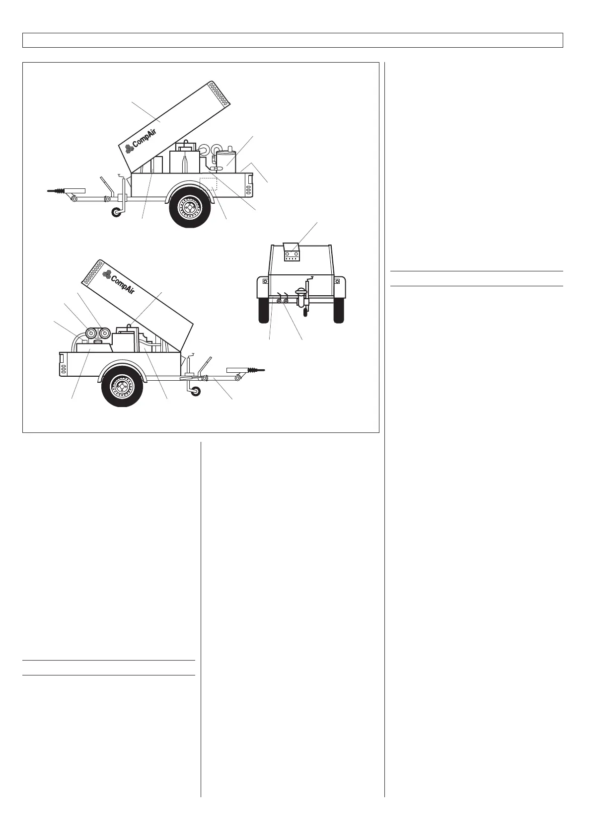
Fig. 3
1. Screw compressor
2. Instrument panel
3. Pressure tank
4. Oil cooler
5. Oil filter (compressor)
6. Air filter (compressor)
7. Air filter (engine)
8. Taps
9. Hood
10. Fuel tank
11. Battery
12. Diesel engine
13. Chassis
14. Tool oiler
15. Crane ring
16. Vehicle and chassis type identification
number
4.1 Construction
Compressor and engine
The DLT 0404 series is a sound proofed
mobile compressor system. The core is a
single-stage, oil-flooded screw compressor.
The CompAir screw profile represents the
state-of-the-art. The air is delivered
pulsation-free.
Frame and chassis
The complete compressor unit is
mounted on an easy-to-transport single-
axle chassis. The chassis is equipped
with automatic overrun brakes and
parking brakes, as well as a jockey wheel
adjustable in height.
Airflow
Fresh air is sucked in through the
admission opening at the back of the
compressor. The air intake volume is
air for the engine and for the compressor
too, as well as cooling air for the engine
and for the oil cooler of the compressor.
4.2 Functional description (see fig.4)
Oil circuit
The oil required for sealing and cooling
the rotors as well as for lubricating the
roller bearings is injected into the
compressor (23) from the pressure tank
(13), which is under system pressure. The
difference in pressure between the
pressure tank and the oil injection position
is approx. 1 bar. The oil hereby passes the
oil cooler (20) and the oil filter (19). The
intake control valve (2) is fitted with a non-
return function, so that when the system is
switched off, flooding of the air filter (1) is
prevented.
Air circuit
The intake air flows through the air filter
(1) and the suction control valve (2) into the
compressor (23). During compression, oil is
injected in order to lubricate, cool and seal
the screw rotors. The compressed air-oil
mixture flows into the pressure tank (13).
Centrifugal preseparation of the oil is
ensured through tangential entry into the
tank.
Any remaining oil is separated from the
air in the fine separator.
The compressed air is fed via the Venturi
nozzle (11) / the pressure retention valve
(option) to the compressed air discharge.
The venturi nozzle (11) effectively prevents
the system pressure from falling below the
minimum operating pressure required for
the system to work properly. A temperature
monitoring device (22, 6) as well as an
operational pressure manometer are
integral parts of the air circuit.
The drive assembly is a medium-cooled
diesel engine, which drives the screw
rotors of the compressor by a flexible
coupling.
Shielding (Body)
The shielding consists of a low box
mounted on a base-frame. A cover, which
can be opened wide for servicing is fixed to
the base-frame. The opening of the cover
is effectively supported by pneumatic
springs. The hook inside is for hanging up
a load suspension device. The machine
rests on rubber elements to prevent
vibrations and noise.
For convenient assembly, all individual
parts of the cover are screwed together
with machine screws. For the prevention of
corrosion, the compressor body is fully
galvanised, electrostatically powder coated
and burnt at °C 220. The sound absorbing
mats are inserted and easy to be cleaned.
13
9
15
4
12
10
6
3
7
11
16
1
5
8
2
14
 Loading...

