Do you have a question about the Competition Electronics DH16A-10DT-B and is the answer not in the manual?
This document describes a series of ACCESS CONTROL devices, specifically models DH16A-10DT-B, DH16A-30DT-B, DH16A-50DT-B, DH16A-12DT-B, DH16A-52DT-B, DH16A-62DT-B, and DH16A-83DT-B. These devices are primarily used for secure access control, offering various methods of entry and management.
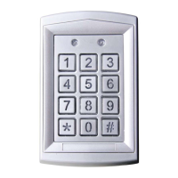
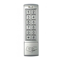
The ACCESS CONTROL devices are designed to manage entry through locks, utilizing a combination of card access, code access, or both. They feature a digital keypad for code entry and an internal EM reader for card-based access. The devices support two independent zones: ZONE 1 and ZONE 2. ZONE 1 can store up to 1000 user cards and corresponding codes, while ZONE 2 can store up to 10 user cards or codes. ZONE 1 offers three modes for opening the lock: card-only access, card or code access, and combined card and code access. ZONE 2 can also be programmed for a door bell function.
The devices incorporate dual relay outputs for door opening, door status detection (for ZONE 1 only), and activation by an external unlock button. A built-in watchdog timer ensures reliable operation with powerful reboot and self-recovery capabilities. The unlock output delay time is adjustable from 0 to 99 seconds.
Working Conditions:
Current and Voltage Requirements:
Applicable Card Mode:
Effective Distance:
Capacity:
Frequency: 125KHz (for all models with internal EM reader)
IP Rating: 65 (indicating protection against dust and low-pressure water jets)
Dimensions:
Digital Keypad Operation: All models feature a digital keypad for entering codes. Card Access, Code Access, and Combined Access: The devices support flexible access methods. Built-in Pickproof Function: Enhances security against tampering. Watchdog Timer: Provides powerful reboot and self-recovery, and can connect with an external unlock button. Dual Relay Outputs: For door opening, door status detection (ZONE 1 only), and activation by button. Unlock Output Delay Time: Adjustable from 0 to 99 seconds. Default Code: The default administrator code is 1234. Admin Code Length: The administrator code can be up to 6 digits long. Access Mode Setting: Users can configure ZONE 1 to operate in card-only, card or code, or combined card and code access modes. Password Length Setting: The length of passwords/code digits can be set from 2 (00-99) to 6 (000-999999). User Card and Code Management (ZONE 1 & ZONE 2):
* button twice.
Unlocking Time Setting (ZONE 1 & ZONE 2): The unlocking delay time can be set from 00 to 99 seconds.
Pickproof Alarm: A built-in buzzer sounds if the photoresistor sensor is exposed to light for 60 seconds, indicating tampering.
Administrator Code Modification: The admin code can be changed by entering the old code twice, followed by the new code.
Turn On/Off Pickproof Alarm: The pickproof function can be enabled or disabled.
Turn On/Off Door Bell: The door bell function (for ZONE 2) can be enabled or disabled.
Master Card Management (ZONE 1 Only):Restoring to Factory Defaults: All user cards and codes can be cleared, and settings restored to factory defaults by pressing * and 8 twice.
Error Information: If incorrect information is entered, the device will indicate with "BI.BI." sounds and will automatically accompany with "BI.BI." sounds after 30 seconds. If not in the setting mode and incomplete numbers are pressed, or if unlock by card and password (combined) but only one action is done, it will turn back in 5 seconds automatically with "BI.BI." sounds.
Disassembly Instructions:
Installation:
Wiring Diagram: The manual provides a detailed wiring diagram for connecting the device, including power (Red-power DC input, Black-power AC input), door status detecting (Brown), unlocking buttons (Orange-unlocking button 1, Yellow-unlocking button 2), and various relay connections (Green-GND, Blue-NO 2, Purple-COM 2, Gray-NC 2, White-NO 1, Pink-COM 1, Aqua-NC 1). A shielded ground connection is also indicated. Pay attention to right polar connection for the door lock.
| Brand | Competition Electronics |
|---|---|
| Model | DH16A-10DT-B |
| Category | IP Access Controllers |
| Language | English |