– This knob controls the highest frequency range that is sent to the
subwoofer(s). The range is adjustable, from 40 to 180 Hz with a third order slope of 18 dB per octave.
The value that this should be set to changes depending on the subwoofer(s), enclosure and vehicle used.
This can be set by starting with the knob position fully clockwise, then turning the knob anti clockwise
very slowly until the best result is heard. This may take some time to get exactly right. It is advisable to
play music of the genre that will most commonly be listened to as this is set. It is also advisable to use
different tracks when configuring the LPF.
When set correctly, the subwoofer is able to work more efficiently, and the upper frequency range
reproduced is configured to the equipment, surroundings and user taste.
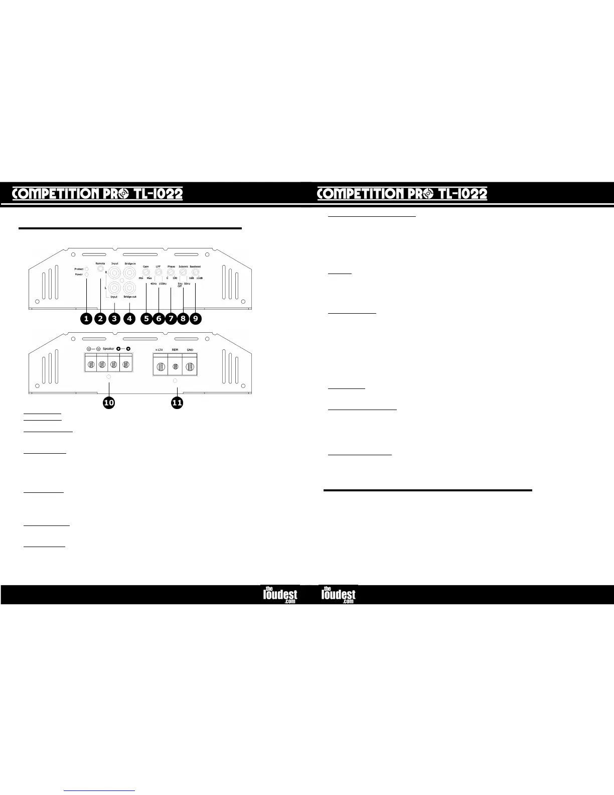
7. Phase – This knob controls the continuously adjustable signal phase lag control of the subwoofers
from 0 to 180 degrees. To find the optimum setting, it is ideal to have one person slowly turning the
knob clockwise (from 0 degrees) fully round to 180 degrees, while the listener is sitting in the vehicle.
The knob should be lest in the optimum position (listen out for smooth bass, bass response and power).
When set correctly, the subwoofer(s) in the vehicle will be adjusted to suit the vehicle and other speakers
in the vehicle.
8. Subsonic Filter – The subsonic filter is the opposite of the LPF; the knob controls the lowest
frequency range that is sent to the subwoofer(s) (effectively a high pass filter). When the knob is turned
fully anti-clockwise, the filter is off. To switch the subsonic filter on, simply turn this knob clockwise,
from which point, the range is adjustable from 5 to 50 Hz with a third order slope of 18 dB per octave.
The value that this should be set to changes depending on the subwoofer(s), enclosure and vehicle used.
This can be set by starting with the knob position fully anti-clockwise, then turning the knob clockwise
very slowly until the best result is heard. This may take some time to get exactly right. It is advisable to
play music of the genre that will most commonly be listened to, as this is set. It is also advisable to use
different tracks when configuring the subsonic filter. For some tastes and situations, the subsonic filter
may not need to be switched on at all.
When set correctly, the subwoofer is able to work more efficiently, and the lower frequency range
reproduced is configured to the equipment, surroundings and user taste.
9. Bass Boost – This knob controls a boost of the bass frequencies at and around 45 Hz. There is no
“bass boost” when the knob is turned fully anti-clockwise. Turning the knob clockwise from this position
boosts the frequencies around the region of 45 Hz by up to 12 dB.
10. Speaker Connections - These are screw terminals for attaching the subwoofer speaker cables.
Undo the screw head enough to slot a stripped end of subwoofer speaker cable into the terminal, and
then tighten the screw. Please see wiring diagrams in the “Installation” section for how to connect
subwoofer speakers to the amplifier. To operate the amplifier in bridge mode, follow the lines printed
next to the terminals on the side of the amplifier. By doing this you connect “CH 1” “+” to “CH 2” “-”.
The minimum load impedance at bridge is 2 ohm, when using both channels, the minimum load
impedance per channel is 1 ohm.
11. Power Connections – This is where all the power leads are connected to the amplifier. Particular
care must be taken when connecting, NOT to cross any of the cables.
“12v” is the positive connection from the battery. “-” is the negative or earth connection and “REM” is
the remote or ignition connection.
somewhere where it will not get damaged, eg. by items in the boot of the vehicle. The amplifier
dissipates heat using its heat sink; somewhere with sufficient space and air would be fine. Therefore
placing the amplifier in between items, placing items on top of it, or mounting it upside down is not
advisable.
Examples of surfaces are: the floor of the boot, fake floor of boot (MDF), side of subwoofer box, or side
of boot. Never mount the amplifier outside of the car, in the engine bay or anywhere where it has a risk
of getting wet. Normally it is best to attach the amplifier to a board, and then attach the board to the car
body. This is good practice to avoid noise problems.
Before mounting, make sure that the surface is suitable and free from any obstructions. Use the
amplifier as a template and mark where the holes are to be drilled with a pencil or pen. Drill the pilot
holes with a drill bit of diameter smaller than that of the screws.
Then place the amplifier on the surface and tighten the screws until they are holding the amplifier
securely in place.
Power indicator - This LED will light when power, remote and earth are all connected to the amplifier. If
this LED is not on, there is a problem with one of these connections.
Protection Indicator - This LED will light if the amplifier has detected a fault and has shut down to protect
itself from permanent damage. This will be due to one of the following: excessive heat, reverse polarity,
short circuit or input overload. If this happens disconnect the amplifier and investigate the problem.
2. Remote Gain – The supplied “Remote Gain Controller” plugs into this socket. With a long run of
cable attached, the gain controller can be positioned in the front of the car so that the level of the output
can be adjusted from the front. Most source units support “fade” function, where the level of the pre-out
signal sent to the amplifier from the source unit can be altered giving exactly the same effect. However,
this provides a hard-wired solution to gain control from the position of the listener. Please see “Gain
Control” notes below. Connection is optional.
3. Audio Input – This section is labelled “Input”, and consists of two RCA phono sockets, one “R” (red)
and one “L” (white), above each other. These are for the audio input. A source unit that supplies a “line
level” (pre amp) audio output in the form of RCA phono plugs is required to connect to the input (via a
phono extension lead). A high quality shielded lead is recommended as this will help reduce the
possibility of noise entering the system.
4. Bridge In/Out – This section consists of two RCA phono sockets, and is only to be used if two of the
TL-1022 amplifiers are used together, sometimes called “strapping” or “bridging”. This can be done very
simply and easily and is explained in detail later on in this manual.
5. Gain Control - Turning the knob to the right (clockwise) will increase the volume, and to the left
(anti-clockwise) will reduce the volume. It is important to understand that the amount of gain
needed is proportional to the level of the signal coming from the source unit. For example, it
is possible for the gain knob to be at only a quarter of its maximum, but the amplifier is
actually outputting to its full potential. This could be because the source unit is supplying
slightly more power than normally expected. Please see “Installation” section for how to calibrate
the amplifier to the output of the source unit using the gain knob.



 To Next Page
 Loading...