Composite-ARF Spitfire 18
Wing assembly (Control horns)Cont.
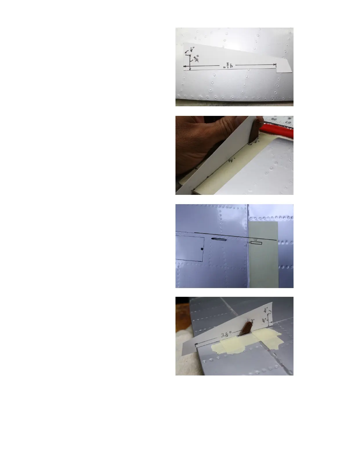
Using a piece of card stock we’ll
make up a jig to align the aileron
control horn. Use the photo as a
guide. Measure back from the front
4 1/2”(114mm) and make a notch as
shown. From the same edge
measure back 1/8”(3mm) and up
from the bottom 3/4”(19mm). This
will be the location of the outer hole
in the control horn. Push a T-pin
through the paper at this location.
Be sure to keep the jig on the line
you made earlier or the control horn
alignment will not be correct. Adjust
the hole in the wing or the length of
the horn if necessary for proper
alignment. Be sure to have at least a
1/2”(13mm) of control horn in the
aileron. When satisfied, scuff the
horn and glue in with reinforced
epoxy.
Next we can do the flap control horn.
Note that the control horn is parallel
to the panel line on the wing, not the
hinge line for the flap. Also note the
panel line is 8 1/4”(209mm) from the
aileron. Transfer the panel line to
the flap as shown in the photo. The
hole for the control horn will be
1/4”(6mm)from this line and
1/4”(6mm) from the hinge line. Mark
for the cutout as shown in the photo.
The cut out is 5/8”(16)mm by
1/8”(3mm). We’ll use the jig made
for the aileron control horns and
remark it for the flap horn as shown.
Measure from the notch 3 1/2(89mm)
forward and up 3/8”(10mm) and
insert T-pin which will be the outer
hole in the flap horn. Make a mark
on the control horn at the surface of the flap. Use as a guide to cut the control
horn to length. There should be a 1/4”(7mm) left inside the flap for gluing.
Continued
 Loading...