Composite-ARF Spitfire 20
Wing assembly (Servo installation)Cont.
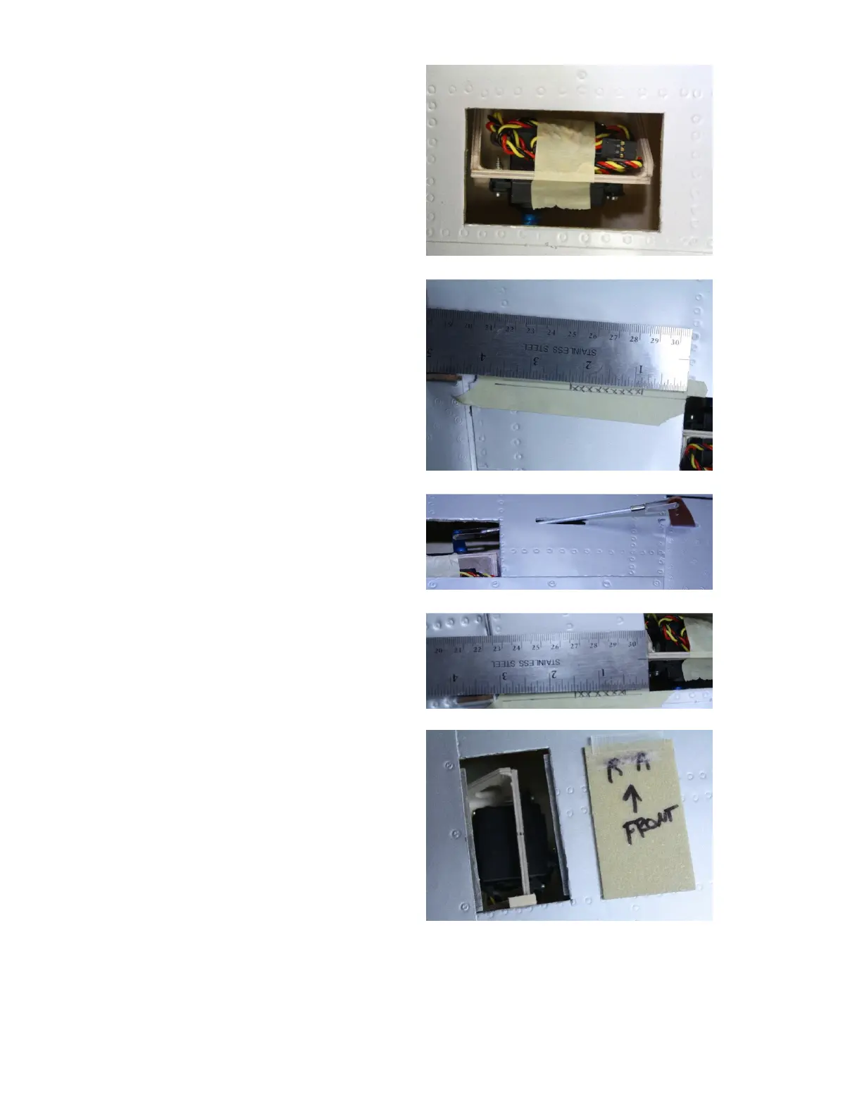
The servo will be centered fore and
aft in the hole, The servo arm will
line up with edge of the pocket as
shown. Scuff the top of the wing
where the servo will be glued. Tape
the servo lead to the servo so you do
not get glue on it. and glue into
position. Use only fiber reinforced
epoxy here. Once the glue has
cured we can cut the hole for the
push rod
Use the photo as a guide to locate
the position of the push rod exit.
We’ll do the aileron first. Mark two
lines from either side of the control
horn to the servo arm. Measure
back from the servo pocket 7/8”(
22mm). This is the front of our hole.
Measure back from here 1
3/8”(35mm). Cut out slot for the
control rod. Use the 3mm threaded
rod supplied in the kit for the push
rod with 3mm clevises as shown.
Note the small relief on the wing, in
front of the control horn for additional
aileron throw.
Use the same method for the flap
control rod with the following
measurements. From the servo
pocket back, measure 1/2”(13mm) to
the front of the slot. From here
measure back 1”(25mm). Cut out a
slot and make control rod as you did
for the aileron.
We can now trim out the pockets for
installation of the cover. Use two
3/8” (10mm)strips of either 1/32”
plywood or poly ply along the sides
of the pockets. Be sure to only have 1/16 (1.5mm) showing in the pocket or you
will not be able to remove the servo. Apply a small piece to the front of the cover
as shown.
Continued
Aileron shown above
 Loading...