13COMPRAG Screw air compressor F-Series
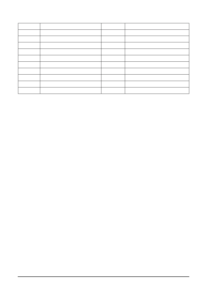
Main components
1 Electric motor 12 Non-return valve
2 Belt drive 13 Heat-exchanger, Air section
3 Air end 14 Heat-exchanger, Oil section
4 Air lter 16 Oil lter
5 Intake valve 17 Drain valve
6 Air-Oil separation tank 18 Oil lling plug
7 Safety valve 19 Oil level sight glass
8 Air-Oil separator 20 Air outlet valve
9 Throttle valve 21 Refrigerated dryer (ARD only)
10 Non-return valve 22 Pressure vessel
11 Min. Pressure valve
2.4 Functional description (see Fig. 2.1 and Fig. 2.2)
Air ow: Air drawn through Air lter (4) and open Intake valve (5) into compressor Air-end (3) is compressed.
Compressed air and oil ow into Air-Oil separation tank (6). The air is discharged via Min.
Pressure valve (11) through Heat-exchanger (13) towards the Air Outlet Valve (20).
Oil ow: Air pressure forces oil from the air-oil separation tank (6) through the heat-exchang-
er (14) and the oil lter (16) to the compressor air-end (3) and the lubrication points. In the
air-oil separation tank (6), most of the oil is removed centrifugally; the rest is removed by
the air-oil separator (8). The oil system is tted with a thermostatic valve (15). When the oil
temperature is below the set-point of the thermostatic valve, the thermostatic valve shuts
off the oil supply from oil heat-exchanger (14). The thermostatic valve starts opening the
supply from heat-exchanger (14) when the oil temperature exceeds the valve’s setting. The
setting of the thermostatic valve depends on the model. See table Technical Data.
Cooling system: The cooling system comprises a combined air section (13) and an oil sec-
tion (14) heatexchanger. A cooling fan, mounted in the fresh air intake section, generates
the cooling air in order to cool the heat-exchanger.