15COMPRAG Screw air compressor F-Series
2.6 Electrical diagram and main components
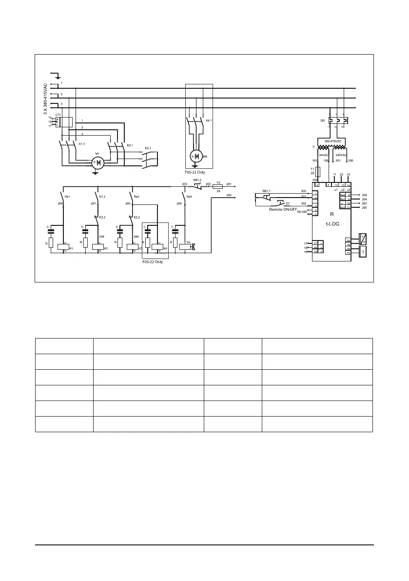
Fig. 2.5 Electrical diagram F05.. – F22.., FR05.. – FR22.., FRD05.. – FRD22..*,
*For RDX Electrical diagram refer to the relevant documentation.
Main components
К1, K2, К3, К4 Contactor YA Solenoid valve
М1 Electric motor R Electronic controller
Т Temperature sensor I/P Pressure sensor
SB Emergency stop CT1 Transformer
F1, F2 Fuses TR Transformer
М2 Fan motor QS Automatic power switch