13
J1
3 2 1
24V - 12V
J1
3 2 1
12V - 24 V
RX
24V - 12V
TX
1 2 3
J1
1 2 3
J1
+
0V NA NCCOM
+12V/24V
+12V/24V
0V
0V
14
RX
TX
RX
TX
Thank you for choosing a COMUNELLO AUTOMATION
product.
This manual provides all the detailed information required for
the knowledge and correct use of the equipment. It must
be read carefully at the time of purchase and consulted if
there are any doubts regarding its use or when maintenance
is required.
The manufacturer reserves the right to make any modica-
tions to the item and to this document without prior notice.
WARNINGS
Please read this manual carefully before beginning instal-
lation and carry out the procedures as specied by the
manufacturer.
This installation manual is only intended for professional
personnel.
Anything not expressly included in these instructions is
prohibited.
In particular, your attention should be drawn towards the fol-
lowing warning:
• Disconnect power before making any electrical connections.
PRODUCT DESCRIPTION AND INTENDED USE
The DART photocell, which uses simple and eective elec-
tronics, is suitable for all types of systems and conditions.
PRELIMINARY CHECKS
• Check that the item inside the packaging is intact and in
good condition.
• Ensure that the positioning of the photocells allows for cor-
rect installation and securing of the photocells (Fig. 3).
• Ensure that the photocells are positioned on parallel surfac-
es and that they are all at the same height.
ELECTRICAL SPECIFICATIONS (RX AND TX)
Optical range under optimal conditions 15 m
IP protection rating 54
Transmitter
Frequency modulation: 330 Hz
Infrared emission wavelength: 950 nm
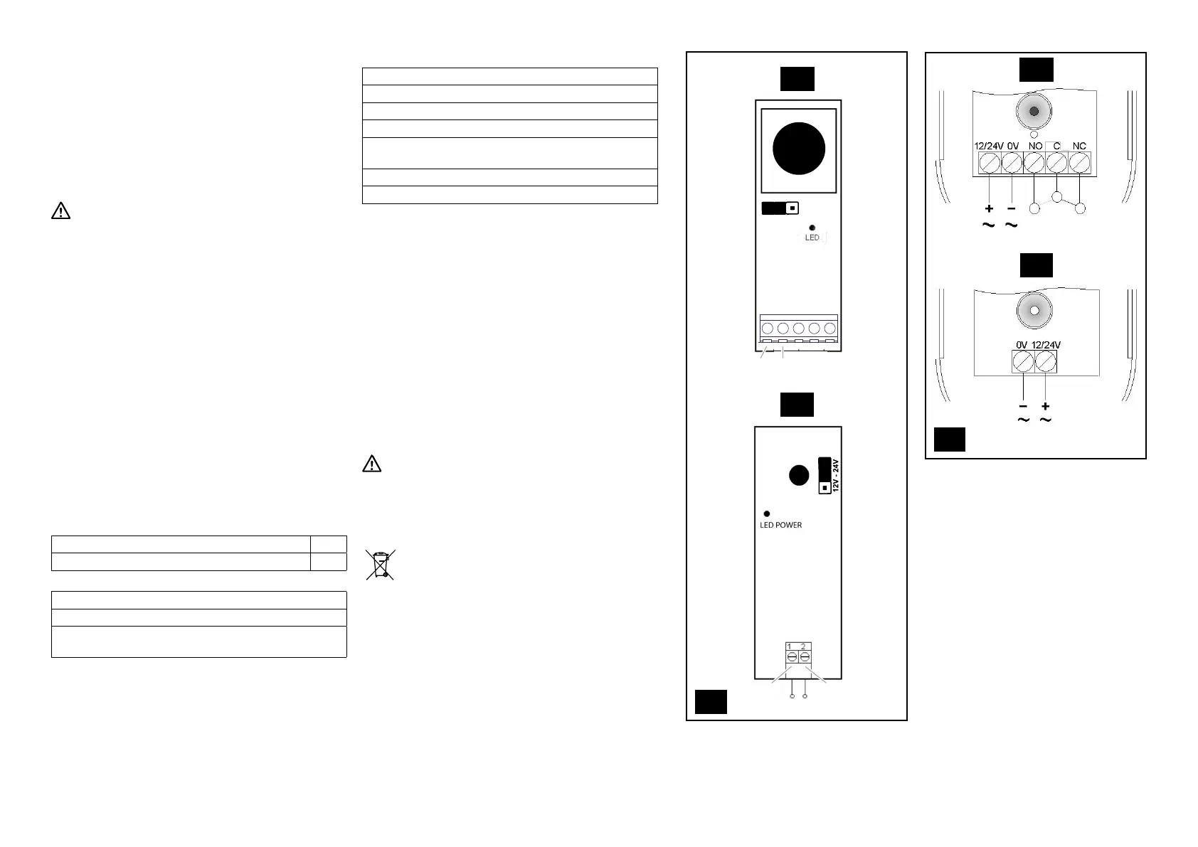
J1 (jumper 1): position 2-3 if power supply to 12V / position
1-2 if power supply to 24V (Fig. 13)
Receiver
Relay contact rating: 1A max at 30Vdc
Normally open contact output: NO
Normally closed contact output: NC
Red LED switches o with photocells aligned
J1 (jumper 1): position 1-2 if power supply to 12V / posi-
tion 2-3 if power supply to 24V (Fig. 13)
Maximum range under optimal conditions: 15 m
Temperature: -20 °C +50 °C
INSTALLATION AND ELECTRICAL CONNECTIONS
Operation with facing transmitter and receiver. Double safety
relay.
• Proceed as shown in Figure 4-5.
• Depending on the cable routing position, drill holes in the
base in the prearranged area (see Fig. 6).
• Proceed as shown in Figure 7 using rawlplugs (Ø max
5 mm) and corresponding screws (not included).
• Connect the cables in the terminals according to the dia-
gram (Fig. 14): 4 on the RX photocell and 2 the TX photo-
cell, from the respective control unit input.
• Apply silicone to seal the cable entry hole (Fig. 8).
• Before closing the photocell, test the transmitter (TX pho-
tocell) with the receiver (RX photocell) and check on the
receiver that the red alignment light (LED1) switches o
(Fig. 9).
• Proceed as shown in Figure 10-11.
TESTING
Test for the correct operation of the photocells.
BOARD REPLACEMENT
If required, replace the board as shown in Figure 12.
DISPOSAL
A number of components of the item can be recycled
while others, such as electronic components, must
be disposed of according to the regulations in force
in the are of installation.
A number of components may contain pollutants that must
not be released into the environment.
 Loading...