EasyManua.ls Logo

Context Plus CAST XFP Series - User Manual

Context Plus CAST XFP Series
24 pages
Print Icon
To Next Page IconTo Next Page
Loading...
CAST XFP
Networkable
Analogue Addressable
Fire Alarm Control Panel
1 Loop 16 Zone Panel
Part No. XFP501E/CA/CON
1 Loop 32 Zone Panel
Part No. XFP501/CA/CON
2 Loop 32 Zone Panel
Part No. XFP502/CA/CON
User Manual
& Log Book
Approved Document No. DFU5020020 Rev 2 16/06/2021
R
Question and Answer IconNeed help?

Do you have a question about the Context Plus CAST XFP Series and is the answer not in the manual?

Summary

Safety and General Information

Symbols and Important Notes

Explains symbols and provides crucial operational notes for safe use.

Important Safety Notes

Details critical safety precautions to be observed before operating the product.

Disclaimer

Outlines limitations of responsibility and policy on product specification changes.

Introduction to the CAST XFP System

Fire Alarm Systems Overview

Provides a general explanation of fire alarm systems and their purpose.

The CAST XFP Fire Alarm Control Panel

Introduces the CAST XFP panel, its capabilities, and features.

Panel Access Levels Overview

Explains the different access levels (1, 2, and 3) and their general functions.

User Responsibilities and Testing Procedures

BS5839-1 User Responsibilities

Summarizes the duties of the responsible person according to BS5839-1.

Routine Weekly User Testing

Details the weekly tests required for the fire alarm system.

Routine Monthly User Testing

Outlines the monthly checks to be performed by the responsible person.

Periodic Inspection and Maintenance

Describes the requirements for ongoing system servicing and maintenance.

Panel Layout and Controls

16 Zone Panel Layout

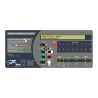
Illustrates and describes the front panel of the single loop, 16 zone fire panel.

32 Zone Panel Layout

Illustrates and describes the front panel of the one or two loop, 32 zone fire panel.

Panel Components and Operation

LED Indicators Explained

Describes the function and meaning of each LED indicator on the panel.

Button Controls Functionality

Explains the purpose and operation of each control button on the panel.

Keyswitch Control Operation

Details how to use the panel's keyswitch to access different levels.

General User Operation and Panel Messages

Understanding Panel Messages

Explains the various messages displayed on the panel during operation.

Normal Operating Conditions

Describes the messages displayed when the system is in a normal state.

Fire Condition Responses

Single Zone Fire Condition

Explains how the panel indicates and responds to a fire in a single zone.

Multiple Zone Fire Condition

Details the panel's response when fires occur in multiple zones simultaneously.

Fire Conditions with Output Delays

Describes how output delays affect the panel's fire condition reporting.

1 st-Stage Fire Conditions

1 st-Stage Fire Event Handling

Explains how the panel manages 1st-stage fire events, including dependency and delay.

Zone Dependency Function

Details how zone dependency affects 1st-stage fire conditions.

Investigation Delay Period

Explains the investigation delay feature for 1st-stage fire conditions.

Initiating Investigation Delay

Guides users on how to start the investigation delay period.

Fault Conditions and Handling

Understanding Fault Messages

Explains what fault messages appear on the panel and their meaning.

Responsible Persons Actions for Faults

Lists the immediate actions required by the responsible person upon a fault.

Access Level 1 Operations

Access Level 1 Capabilities

Lists the actions a general user can perform at access level 1.

Entering Access Level 2

Provides instructions on how to access level 2 from level 1.

Entering Access Level 3

Warns against accessing access level 3 and directs engineers to a separate manual.

Displaying Fire Events

Explains how to view fire events at access level 1.

Access Level 1 Menu Options

Displaying Fault Events

Describes how to view fault events at access level 1.

Displaying Disablements

Explains how to view system disablements at access level 1.

Displaying Zones in Test

Details how to view zones currently in test mode at access level 1.

Testing Panel Lamps

Guides users on performing a lamp test to verify indicator functionality.

Displaying Alarm Counter

Explains how to view the panel's total fire alarm counts.

Access Level 2 Operations

Access Level 2 Capabilities

Lists the functions available to authorised users at access level 2.

Entering Access Level 2 via Pushbuttons

Instructions for gaining access level 2 using the panel's keypad.

Entering Access Level 2 via Keyswitch

Instructions for gaining access level 2 using the panel's keyswitch.

Silencing Alarm Sounders

How to silence active alarm sounders once in access level 2.

Resounding Alarm Sounders

How to resound silenced alarm sounders.

Resetting the Panel

Steps to reset the panel after an alarm has been cleared and silenced.

Access Level 2 Menu Functions

Entering Access Level 3

Warning regarding access level 3, directing engineers to a separate manual.

Lamp Test via Access Level 2

How to perform a lamp test using access level 2 functions.

Alarm Counter via Access Level 2

How to display and clear the alarm counter using access level 2.

Access Level 2 System Management

Changing Panel Time and Date

Instructions for adjusting the panel's time and date settings.

Event Log Functions

Overview of accessing and managing the panel's event log.

Displaying Event History

How to view historical events recorded in the panel's log.

Resetting Event History

Steps to clear the panel's event log.

Access Level 2 System Configuration

Set;Clear Disablements Overview

Introduces the functionality for enabling or disabling system components.

Enable;Disable Zones

How to disable or enable specific zones within the system.

Enable;Disable Sounders

How to disable or enable specific sounder groups.

Enable;Disable Outputs

How to disable or enable specific output sets.

Access Level 2 Disable;Enable Functions

Enable;Disable Relays

How to disable or enable auxiliary relays.

Enable;Disable Devices

How to disable or enable individual detectors or call points.

Enable;Disable Fault Relay

How to suppress or enable the fault relay activation.

Enable;Disable Output Delays

How to globally disable or enable output delays.

Access Level 2 Code Management

Changing Access Level 2 Entry Code

Instructions for changing the four-digit access code for level 2.

System Configuration Data

Zone Setup Data Chart

A table for recording zone configuration details like dependencies and output delays.

Access Level 2 Code and Additional Info

Fields for recording the access level 2 code and other essential system information.

Fire Alarm Log Book

Log Book Purpose and Requirements

Explains the importance and mandatory entries for the fire alarm log book.

Service Contact Details

Section for recording essential service and maintenance contact information.

Specific Log Entries

False Alarm Recording

Details for logging false alarms, including cause and circumstances.

Maintenance Work Recording

Details for logging maintenance activities, reasons, and work performed.

Overview

The CAST XFP is a networkable analogue addressable fire alarm control panel designed for comprehensive fire detection and alarm management. It is available in several configurations:

  • 1 Loop 16 Zone Panel: Part No. XFP501E/CA/CON
  • 1 Loop 32 Zone Panel: Part No. XFP501/CA/CON
  • 2 Loop 32 Zone Panel: Part No. XFP502/CA/CON

Function Description:

The primary function of the CAST XFP panel is to provide early warning of fire, facilitate evacuation, and enable timely action to mitigate fire spread. It achieves this by working with a range of CAST-compatible fire detection devices, offering detailed information about fire conditions beyond just the activated zone number. The panel provides prioritized feedback on system status through an easy-to-read 80-character display, indicating the name and location of activated detectors and the order in which they triggered an alarm. It also displays detailed information on fault conditions and can be programmed to reduce false alarms and encourage orderly evacuation during a true fire event.

Usage Features:

The panel offers three access levels:

  • Access Level 1 (General User): Accessible to everyone, this level allows users to scroll through fire or fault conditions, view disablements or zones under test, test panel lamps (LED indicators and display), and determine the total number of fire alarms. Users can also gain entry to Access Level 2 or 3 (if authorized).
  • Access Level 2 (Authorized User): Accessible to trained personnel, this level is entered by inputting a four-digit code or turning a keyswitch to the 'I' position. At this level, the Silence/Resound Sounders, Control Panel Reset, and Investigate buttons become active. Users can scroll through fire/fault conditions, view disablements/zones under test, enable/disable zones, sounders, outputs, relays, and devices, display/reset event history, set time/date, and change the Access Level 2 entry code.
  • Access Level 3 (Engineering/Programming Level): This level is strictly for authorized system engineers. Unauthorized access is strongly discouraged as it can affect panel functionality, endanger life, and void the warranty.

Panel Indicators and Controls:

The panel features various LED indicators and buttons for operation:

  • Liquid Crystal Display (LCD): Provides detailed information on system status, fire, and fault conditions.
  • (General) Fire Indicator: Flashes red during a fire condition, turns steady red when silenced. Restarts flashing for subsequent fire conditions until silenced again.
  • Fire Zones Indicators (1-16 or 1-32): Flash red to indicate the zone(s) in fire, turn steady red when silenced.
  • Supply Present Indicator: Normally lit green, indicating all power supplies are functioning.
  • Test Indicator: Lit yellow when the panel is in walk test mode.
  • Accessed Indicator: Lit yellow when the panel is in Access Level 2 or 3.
  • General Disablement Indicator: Lit yellow when one or more zones, sounders, outputs, or relays are disabled.
  • Phased Evacuation Indicator: Flashes yellow during a phased evacuation.
  • General Fault Indicator: Flashes yellow when a fault condition exists, always lit with another fault indicator.
  • Power Supply Fault Indicator: Lit yellow if the power supply or mains has failed, or the standby battery is in poor condition.
  • System Fault Indicator: Lit yellow for system errors (e.g., microprocessor fault), remains lit even after the fault clears until reset at Access Level 2/3.
  • Sounder Status Indicator: Flashes yellow if a sounder is faulty or disabled.
  • Delays Running Indicator: Flashes yellow when one or more output delays are programmed or running.

Button Controls:

  • More Information: Displays additional details on fire or fault conditions.
  • Scroll Up/Down (▲/▼): Scrolls vertically through fire/fault conditions, user menus, manipulates settings, selects Yes/No options, and serves as code input buttons.
  • Accept (►): Scrolls horizontally through user menus, accepts options, and serves as a code input button.
  • Escape (◄): Scrolls horizontally through user menus, escapes options, and serves as a code input button.
  • Menu: Provides access to the panel's user menus.
  • Silence Internal Sounder: Silences the panel's internal sounder.
  • Control Panel Reset: Resets the panel after alarms are silenced (Access Levels 2 & 3 only).
  • Silence / Resound Sounders: Silences or resounds system sounders (Access Levels 2 & 3 only).
  • Investigate: Starts the panel's investigate timer function (Access Levels 2 & 3 only), if enabled by an engineer.
  • Keyswitch Control: Turning the keyswitch to 'I' provides instant Access Level 2.

Important Technical Specifications (Implied from manual content):

  • Display: 80-character display.
  • Event Log Capacity: 499 events.
  • Alarm Counter: Maximum 999 counts.
  • Access Code: Four-digit code for Access Level 2 (default 3333).
  • Networking: "Networkable" implies multi-panel system integration.
  • Addressable: Works with "addressable" fire detection devices, providing specific device information.
  • Zones: Available in 16-zone and 32-zone configurations.
  • Loops: Available in 1-loop and 2-loop configurations.

Maintenance Features:

  • Routine Weekly Testing: Recommended to check all zone lights, internal sounder, operate a manual call point or detector, check alarm sounders, reset the system, and verify unobstructed call points/detectors. Contacting the alarm receiving center before and after tests is crucial.
  • Routine Monthly Testing: Authorized service personnel should verify the system's standby power supply/batteries.
  • Quarterly and Periodic Inspection, Testing, Servicing, and Maintenance: Requires a competent person with specialist knowledge, typically an outside specialist fire alarm servicing organization, to meet BS5839-1 Clause 45 requirements.
  • Fire Alarm Log Book: Essential for recording fire signals, fault signals, system work, and maintenance. This helps satisfy BS5839-1 recommendations and legal requirements.
  • Lamp Test: Allows users to test all LED indicators and the display to ensure they are working correctly.
  • Alarm Counter Reset: The alarm counter can be reset at Access Level 2 to track new fire conditions from a specific date.
  • Event Log: Records system events, which can be displayed and reset by authorized users.
  • Disablement Functions: Authorized users can temporarily disable zones, sounders, outputs, relays, and individual devices for maintenance or to address nuisance tripping.
  • Fault Reporting: The panel displays detailed fault messages and device-specific information to aid in rectification.

Safety Notes:

  • Read instructions thoroughly before operation.
  • Hazardous voltages are present inside the panel; do not operate with the enclosure open.
  • Only competent service personnel should perform commissioning, maintenance, and remedial work, being fully conversant with the Installation and Programming Manual.
  • Seek expert advice if the panel is damaged.
  • Regular servicing by a competent organization is highly recommended.
  • The building's fire management plan should always be executed in the event of a fire condition.
  • Unauthorized access to Access Level 3 is strictly prohibited to prevent system malfunction, danger to life, and warranty voidance.

Context Plus CAST XFP Series Specifications

General IconGeneral
BrandContext Plus
ModelCAST XFP Series
CategoryControl Panel
LanguageEnglish