EasyManua.ls Logo

Continental Electric WA-9000 - User Manual

Default Icon
66 pages
Print Icon
To Next Page IconTo Next Page
Loading...
Seaim _nvlcisa "_alning and Edu_etion
I
Electric
Included in this manual is all available information covering
the Continental portable air conditioners. Models are being
sold outside the U.S. as well as inside the U.S. Although the
units may have different model numbers, both the customer
and service information are the same. Listed below are the
European model numbers and the corresponding U.S. model
numbers:
European Model # U.S. Model #
PAC-800 CE71096
PAC-88 CE72096
PAC-88E CE73096
WA-9000 CE75096
WA-9000E CE76096
WA-9000ER CE77096
WA-12000 CE75126
WA-12000E CE76126
WA-12000ER CE77126
Sears Services Training and Education
© 2000 Sears, Roebuck and Co.
Question and Answer IconNeed help?

Do you have a question about the Continental Electric WA-9000 and is the answer not in the manual?

Summary

DESCRIPTION OF COMPONENTS

Front and Rear Unit Views

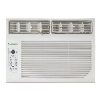
Diagrams labeling the front and rear parts of the air conditioner.

Control Panel Dial Layout

Illustration of the timer, speed, and thermostat controls.

Control Panel Description

Indicator and Button Labels

Labels for indicators, buttons, and the digital display on the control panel.

DESCRIPTION OF OPERATION

Exhaust Duct Set Installation

Instructions for connecting the exhaust hose using the duct set.

Window Panel Kit Installation

Panel Assembly Steps

Steps for assembling and installing the window panel kit.

NOTES IN OPERATION

UNIQUE ADVANTAGES OF THIS MODEL

Exploded View Diagram

Parts List - PAC-800 (CE71096)

Safety Warnings

General Safety Precautions

Critical guidelines for safe handling and operation of the appliance.

Indoor Unit Components

External Part Identification

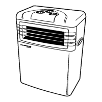
Labels identifying the external parts of the indoor unit.

Accessories and Outdoor Unit

Accessory List

List of included accessories with their descriptions.

Outdoor Unit Parts

Labels identifying components of the outdoor unit.

Operating Controls

Control Panel Layout

Diagram showing the layout of controls on the unit's panel.

Operational Cautions

Important notes and warnings regarding unit operation.

Control Panel Modes

Fan Operation Controls

Controls for operating the unit in fan-only mode.

Air-Conditioning Controls

Controls for operating the unit in air-conditioning mode.

Remote Control Functions

Remote Control Operation

Explanation of buttons and functions on the remote control.

Maintenance Procedures

Filter Cleaning

Instructions for cleaning the air filter.

Unit Cleaning

Steps for cleaning the unit's exterior and housing.

End of Season Storage

Procedures for storing the unit safely after the season.

Energy Saving Tips

Filter Maintenance for Efficiency

Importance of filter cleaning for optimal performance.

Improving Operational Efficiency

Tips to save energy and maximize cooling efficiency.

Quick Connector Service

Disassembly of Connector

Step-by-step guide to disconnecting the quick connector.

Connection of Connector

Step-by-step guide to reconnecting the quick connector.

Installation Guide

Indoor Unit Placement Methods

Different methods for installing and positioning the indoor unit.

Heat Exhaust Hose Installation

Exhaust Duct Set Method

Instructions for using the exhaust duct set to install the hose.

Window Panel Kit Method

Instructions for using the window panel kit to install the hose.

Outdoor Unit Installation

Outdoor Unit Placement Methods

Methods for installing the outdoor unit in various locations.

Troubleshooting Guide

Common Problems and Solutions

Table listing common issues, their causes, and resolution steps.

Service Manual Overview

Product Specifications

Cooling System Diagrams

System Operating Diagram

Flowchart illustrating the cooling system operation.

Wiring Diagrams

Schematic diagrams showing electrical connections.

Reason of Breakdown and Solution

Troubleshooting Table

List of common malfunctions, causes, and solutions.

Cooling System Flow Chart

WA-9000 Air Conditioner Parts List

WA-9000 E;WA-9000 ER Parts List

SPECIFICATION

Cooling System Diagrams

System Operating Diagram

Flowchart illustrating the cooling system operation.

Wiring Diagrams

Schematic diagrams showing electrical connections.

Reason of Breakdown and Solution

Troubleshooting Table

List of common malfunctions, causes, and solutions.

Cooling System Flow Chart

WA-12000 Series Parts List

Continental Electric WA-9000 Specifications

General IconGeneral
BrandContinental Electric
ModelWA-9000
CategoryAir Conditioner
LanguageEnglish

Related product manuals