EasyManua.ls Logo

Contrel ELR-7 - User Manual

Contrel ELR-7
4 pages
Print Icon
To Next Page IconTo Next Page
Loading...
ELR-7 manuale istruzioni / instruction manual IM205-IU v1.6 pag. 1
MANUALE ISTRUZIONI / INSTRUCTION MANUAL
IM205-IU v1.6
ELR-7 RELÈ DIFFERENZIALE DI TERRA / EARTH LEAKAGE RELAY
Relè differenziale di terra elettronico
di dimensioni compatte (esecuzione
da incasso DIN 48x48mm) con ampia
regolazione dei parametri di taratura.
Earth Leakage Relay with compact
dimensions (flush mouting DIN
48x48mm) and wide possibility of
parameters regulations.
GENERALITÀ
Il relè ELR-7 è un dispositivo differenziale che, pur
mantenendo l'ampiezza della taratura in corrente e
tempo dei relè della serie ELR e mantenendo le stesse
elevate prestazioni, è inserito in un contenitore per
montaggio da incasso DIN 48x48mm e profondità ridotta
a 72mm comprese le morsettiere.
Tutto questo permette di ridurre al minimo l’ingombro in
quelle applicazioni dove gli spazi sono limitati, come nei
quadri MCC, mantenendo prestazioni adeguate anche
alle installazioni più critiche.Risulta quindi adatto alla
protezione carichi critici, come grandi motori, ecc.
Come per tutta la gamma dei relè ELR questo modello
incorpora degli opportuni filtri sui circuiti di ingresso
rendendolo praticamente immune dai disturbi esterni ed
un'elettronica di controllo permanente dell'efficienza dei
circuiti interni e del riduttore toroidale.
Sul fronte sono programmabili la corrente di intervento
(25mA ÷ 25 A), il tempo di intervento (0,02 ÷ 5 sec.) e la
modalità di funzionamento del reset (automatico o
manuale).
Il relè ELR-7 è dotato di un microinterruttore che
permette la selezione del funzionamento del relè finale
normalmente diseccitato a riposo (condizione di non
intervento) o normalmente eccitato (sicurezza positiva o
fail safe).
Il dispositivo è inoltre dotato di due contatti in scambio
separati in uscita (ad esempio uno per la connessione
alla bobina di apertura dell’interruttore e uno per
segnalazione intervento a distanza), una apposita
calotta trasparente di protezione frontale e comode
morsettiere a vite estraibili.
GENERAL
The earth leakage relay ELR-7 is a device inserted in a
flush mounting DIN 48X48 with an extreme depth of
72mm terminals included, keeping in the same time both
the trip current and delay time adjustment amplitude of
relays series ELR keeping the same high performance.
All that allows to minimize the dimensions in all the
applications where we have place, gaps, like in MCC
electrical panel board.
As for all the ELR series this one has implemented
several filters on the input section, making it insensible
to external disturbances and also a self diagnostic check
of the internal circuits and the external toroidal current
transformer.
For all these reason it is recommended for the protection
of big motors and critical loads.
On the front label it is possible to set the tripping current
(0.025 ÷ 25A), the delay time(0,02 ÷ 5 sec.), the fail safe
and reset modality.
The device is also equipped with two change-over trip
contacts (example the first one for connection to the
shunt trip, the second for remote signalization),and also
with a plastic cover.
Another important feature is the possibility to draw-out
the terminal-board.
MODELLI DISPONIBILI
Sono disponibili due modelli che si differenziano in base
all’alimentazione ausiliaria:
- ELR-7 110-230V 50-60 Hz 110 Vcc
- ELR-7 24-48V 50-60 Hz 24-48 Vcc
- ELR-7 220Vcc
EXECUTIONS
According to the auxiliary power supply are available
two executions:
- ELR-7 110-230V 50-60 Hz 110 V dc
- ELR-7 24-48 V 50-60 Hz 24-48V dc
- ELR-7 220Vdc
Question and Answer IconNeed help?

Do you have a question about the Contrel ELR-7 and is the answer not in the manual?

Overview

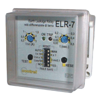
The ELR-7 is an electronic earth leakage relay designed for flush mounting in a DIN 48x48mm enclosure. It features compact dimensions and extensive adjustability for its operating parameters.

Function Description

The ELR-7 earth leakage relay is a protective device that maintains the broad adjustment range for current and time settings characteristic of the ELR series, while also offering high performance. Its compact design, with a depth of 72mm including terminals, allows for installation in applications with limited space, such as MCC electrical panel boards.

The relay is suitable for protecting critical loads, including large motors. It incorporates input circuit filters to minimize susceptibility to external disturbances and includes a self-diagnostic system for continuous monitoring of its internal circuits and the external toroidal current transformer.

On the front panel, users can program the tripping current (ranging from 0.025A to 25A), the delay time (from 0.02 seconds to 5 seconds), and the reset mode (automatic or manual). The device also features a microswitch that allows selection between normally de-energized (non-tripping condition) or normally energized (fail-safe) operation for the final relay.

The ELR-7 is equipped with two independent change-over output contacts. One contact can be used for connection to a shunt trip coil for circuit breaker operation, while the other can be used for remote signaling of a trip event. A transparent plastic cover provides front protection, and the device utilizes convenient plug-in screw terminals.

Important Technical Specifications

Power Supply Voltage:

  • 110-230V 50-60Hz / 110Vdc
  • 24-48V 50-60Hz / 24-48Vdc
  • 220Vdc

Max Consumption: 3 VA

Tripping Current Adjustment (IΔn):

  • 0.025 ÷ 0.25 A (for K=0.1)
  • 0.25 ÷ 2.5 A (for K=1)
  • 2.5 ÷ 25 A (for K=10)

Delay Time Adjustment (t):

  • 0.02 ÷ 0.5 sec. (for K=1)
  • 0.2 ÷ 5 sec. (for K=10)

External Toroidal Current Transformers and Accessories: CT-1 series (external multiplier setting, CT adapter)

Output Contacts: 2 change-over contacts NO-C-NC, 5A 250V resistive load

Operating Temperature: -10 ÷ 60°C

Storage Temperature: -20 ÷ 80°C

Relative Humidity: ≤ 90%

Insulation Test: 2.5 kV 60 sec.

References Standard: CEI 41-1, IEC 255, VDE 0664

Electromagnetic Compatibility: CEI-EN 50081-1, CEI-EN 50082-2

Assembly Position: Any

Type of Connection: By removable terminal strip, max 2.5 mm² cable section

Protection Class:

  • IP40 front with cover (optional IP55)
  • IP20 enclosure

Mounting: Flush mounting DIN 48x48mm, depth 72mm

Usage Features

Programming and Settings: The front panel includes several controls for setting the relay's parameters:

  1. Tripping Current Adjustment Potentiometer: Used to set the desired tripping current (IΔn).
  2. Delay Time Adjustment Potentiometer: Used to set the desired delay time (t).
  3. DIP Switches for Setup:
    • Switch 'a': Position 1 for automatic reset, Position 0 for manual reset.
    • Switch 'b': Selects the constant for delay rating. Position 1 for K=10, Position 0 for K=1.
    • Switches 'c' and 'd': Selects the constant for current rating.
      • Positions 0,0 for K=0.1
      • Position 1,0 for K=1
      • Positions 1,1 for K=10
    • Switch 'e': Determines the output relay state. Position 1 for normally de-energized output relays (non-tripping condition), Position 0 for normally energized output relays (fail-safe).
  4. Test Push-Button: For testing the relay's functionality.
  5. Manual Reset Push-Button: For manually resetting the relay after a trip.

Indicators:

  • Green LED (6): Indicates auxiliary voltage supply presence.
  • Red LED (7): Indicates a tripped relay.

Connections:

  • Output Relays Terminals (8): For connecting to external devices like shunt trips or remote signaling.
  • Auxiliary Voltage Supply Terminals and Connection to External Toroidal Current Transformer (9): For power input and current transformer connection.

Optional Features:

  • 3rd Harmonic Filter: An optional internal filter (approx. -22dB at 150Hz) can be added for applications on 50-60Hz lines. This version is designated with an 'h' suffix (e.g., ELR-7h).
  • IP55 Front Protection: A special plastic cover with a gasket can be requested to achieve IP55 front-side protection.

Accessories: The ELR-7 is compatible with accessories from the entire ELR series, such as external multipliers (CT1-M type) and adapters for connection with current transformers (e.g., .../5A).

Wiring Recommendations: For connecting the toroidal current transformer to the relay, it is recommended to use twisted pair or shielded cables to minimize interference.

Maintenance Features

The ELR-7 is designed with features that simplify maintenance and ensure reliable operation:

  • Self-Diagnostic Check: The device continuously monitors its internal circuits and the external toroidal current transformer, alerting users to potential issues.
  • Test Push-Button: Allows for quick and easy testing of the relay's tripping function, which is crucial for verifying its operational integrity without needing to simulate an actual fault.
  • Removable Terminal Strip: The plug-in screw terminals facilitate easy wiring and disconnection, simplifying installation and replacement procedures. This design allows for the relay to be removed or replaced without disturbing the wiring.
  • Transparent Front Cover: Provides protection for the settings and indicators while allowing for visual inspection of the LED status and parameter configurations.
  • Robust Design: Built to CEI, IEC, and VDE standards, ensuring durability and reliability in various operating environments.
  • Wide Operating Temperature Range: -10 to 60°C, suitable for industrial applications.
  • Storage Temperature Range: -20 to 80°C, allowing for storage in diverse conditions.

Contrel ELR-7 Specifications

General IconGeneral
BrandContrel
ModelELR-7
CategoryRelays
LanguageEnglish

Related product manuals