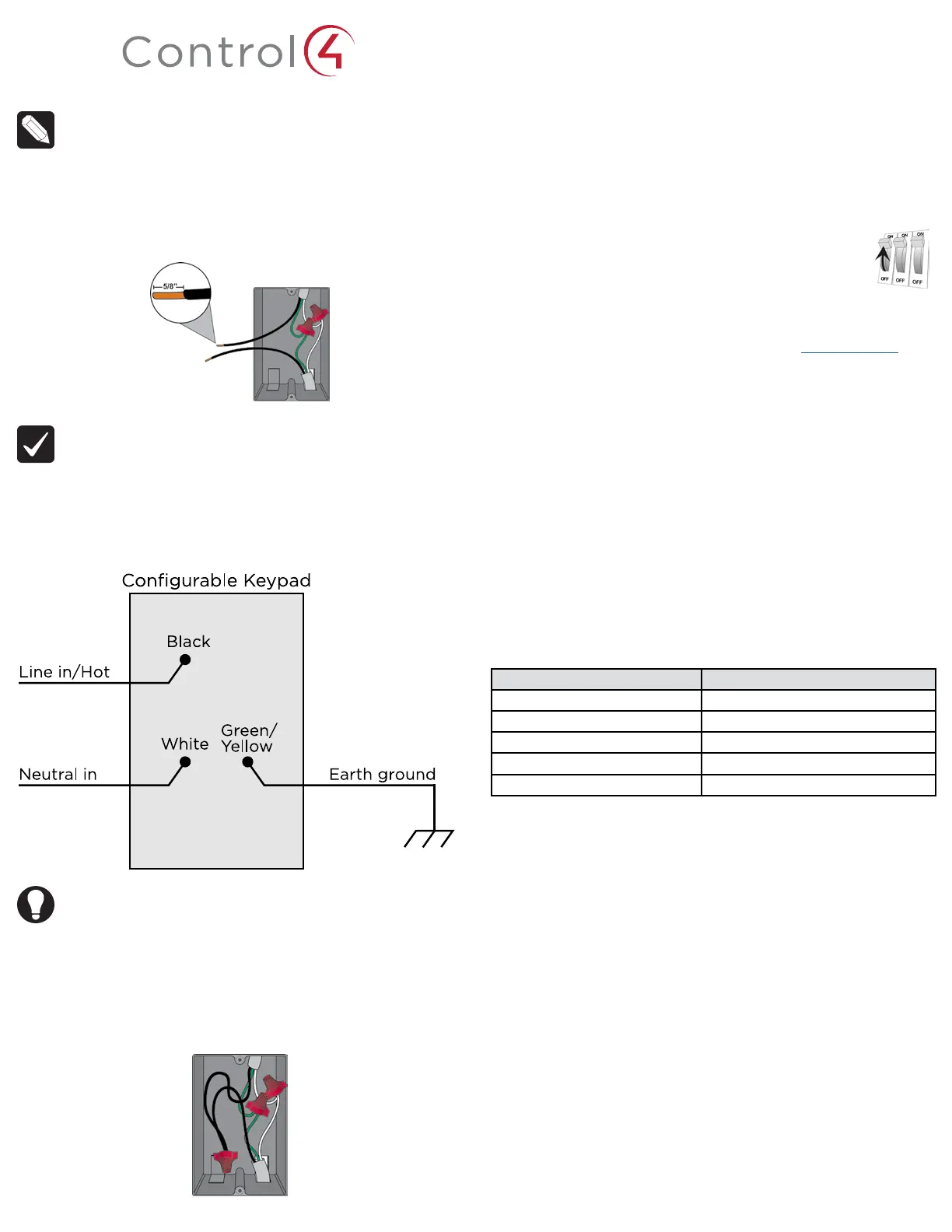
NOTE: The wallbox wiring shown in this document is an example. Your
wire colors and functions may dier. If you are not sure which wires are
the Line In/Hot, Neutral, and Earth Ground wires, have a trained electrician
do the installation.
3 Prepare each wire. Wire insulation should be stripped back 5/8 of an inch
from the wire end (see Figure 1).
Figure 1.
Strip wire insulation
IMPORTANT! Not grounding this product, as described in the section,
“Warnings and Considerations,” may result in an installation less immune
to damage caused by electrical disturbances, such as ESD or lightning,
and may void the warranty.
4 Identify and connect the keypad wires to the wallbox wires using the wire
nuts as shown in Figure 2 below.
Figure 2. Keypad wiring
TIP: If you are using a Control4 push-on (screwless) faceplate in a multi-
gang installation, attach the black faceplate sub-plate to all of the devices
that will be installed into the wallbox prior to attaching the devices to the
wallbox. This will help ensure that all the devices are properly aligned and
on the same plane after installation.
5 Fit the wires back into the wallbox. Bend the wires in a zigzag pattern so that
they easily fold into the wallbox (Figure 3).
Figure 3.
Bend the wires
6 Align the keypad to the wallbox (the model # label should be at the bottom)
and fasten it with screws. Tighten the screws until the back side of the yoke
plate is even with the wall surface, but no further. Overtightening can warp
the configurable keypad and cause mechanical malfunction.
7 Install the Top Actuator Bar, Bottom Sensor Bar, and buttons following the
instructions in the “Button Installation” section below.
8 Install the Control4 Faceplate following the instructions in the Faceplate
Installation Guide or attach a standard Decora-style faceplate.
9 Turn on power at the circuit breaker or replace the fuse from
the fuse box.
Low-voltage bus installation
This device may also be powered by a low-voltage wired keypad bus. Refer to
Figure 4 on the next page. For details on bus wiring, visit: ctrl4.co/buswiring
Button installation
For information about how to install or remove the buttons on the configurable
keypad, see the Keypad Buttons Installation Guide.
Operation and configuration
On initial power up, all status LEDs on the keypad will illuminate green indicating
that the device has power. Until the keypad has been configured into a Control4
system, it will not control any loads. To set up this keypad for use with a Control4
system, refer to the Composer Pro User Guide.
Button tap sequences
The button tap sequences are defined in the table below. Button tap sequences
that require a single (1) button should use the top-most button installed on the
keypad. Button tap sequences requiring two (2) buttons should use the top-most
and bottom-most buttons installed on the keypad.
Function Button sequence
Identify 4
Zigbee channel 7
Reboot 15
Factory reset 9-4-9
Leave mesh and reset 13-4-13
Troubleshooting
If the LEDs do not light up indicating that the keypad is receiving power::
• Ensure circuit breaker is not turned OFF or tripped.
• Check for proper wiring (see Step 2 in “Installation Instructions”).
Care and cleaning
• Do NOT paint the keypad or its wall plate.
• Do NOT use any chemical cleaners to clean the keypad.
• Clean surface of the keypad with a soft damp cloth as needed.
Warranty and legal notices
Find details of the product’s Limited Warranty at snapav.com/warranty or request
a paper copy from Customer Service at 866.424.4489. Find other legal resources,
such as regulatory notices and patent information, at snapav.com/legal.

 Loading...