EasyManua.ls Logo

Control 4 C4-KA - User Manual

Control 4 C4-KA
2 pages
Print Icon
To Next Page IconTo Next Page
Loading...
Warnings and Considerations
WARNING! Turn OFF electrical power before installing or servicing this
product. Improper use or installation can cause SERIOUS INJURY, DEATH
or LOSS/DAMAGE OF PROPERTY.
ATTENTION! Coupez l’alimentation électrique avant d’installer ou de
réparer ce produit. Une mauvaise installation ou utilisation peut entraîner
des blessures graves, décès ou perte / dommages à la propriété.
WARNING! This device must be protected by a circuit breaker (20A max).
ATTENTION! Cet appareil doit être protégé par un disjoncteur (20A max.)
WARNING! Ground this device in accordance with the National Electric
Code (NEC) requirements. DO NOT rely solely upon the yoke plate’s
contact with a metal wallbox for adequate grounding. Use the device’s
ground wire to make a secure connection to the safety ground of the
electrical system.
ATTENTION! Cet appareil doit être en conformité avec le Code national
de l’électricité (NEC). Ne comptez pas uniquement au contact de la
plaque avant avec un boîtier mural métallique pour la mise à la terre
adéquate. Utilisez cet appareil à la terre de l’appareil pour établir une
connexion sécurisée au système électrique.
IMPORTANT! This device must be installed by a licensed electrician in
accordance with all national and local electrical codes.
IMPORTANT! If you are unsure about any part of these instructions,
consult a qualified electrician.
IMPORTANT! Use this device only with copper or copper-clad wire. Do
not use aluminum wiring. This product has not been approved for use with
aluminum wiring.
IMPORTANT! Install in accordance with all applicable national and local
electrical codes.
IMPORTANT! Using this product in a manner other than outlined in this
document voids your warranty. Further, Control4 is NOT liable for any
damage incurred with the misuse of this product. See “Troubleshooting.”
IMPORTANT! Do NOT use a power screwdriver to install this device. If you
do, you may overtighten the screws and strip them. Also, overtightening
the screws may interfere with proper button operation.
IMPORTANT! This is an electronic device with intricate components.
Handle and install with care!
Installation Instructions
1 Turn o the local electrical power by either switching o the circuit breaker or
removing the fuse from the fuse box. To ensure the wires do NOT have power
running to them, use an inductive voltage detector.
NOTE: The wallbox wiring shown in this document is an example. Your
wire colors and functions may dier. If you are not sure which wires are
the Hot, Neutral, and Ground wires, have a trained electrician do the
installation.
2 Prepare each wire. Wire insulation should be stripped back 5/8 of an inch
from the wire end (see Figure 1).
Supported Model
đŏ C4-KA Auxiliary Keypad
Introduction
The Control4® Auxiliary Keypad is intended for use in a Control4 system. It installs
in a standard wallbox and connects and communicates with a compatible Control4
dimmer or switch using the traveler wire.
Box Contents
đŏ Auxiliary Keypad
đŏ Wire Nuts
đŏ Warranty Card
đŏ
14%(%.5ŏ!5, ŏ*/0((0%+*ŏ1% ! (this document)
Compatible Devices
The Auxiliary Keypad can connect to and control any of the following Control4
devices:
đŏ C4-APD120 Adaptive Phase Dimmer
đŏ C4-APD240 Adaptive Phase Dimmer
đŏ C4-APD277 Adaptive Phase Dimmer
đŏ C4-FPD120 Forward Phase Dimmer
đŏ C4-KD120 Keypad Dimmer
đŏ C4-KD240 Keypad Dimmer
đŏ C4-KD277 Keypad Dimmer
đŏ C4-SW120277 Switch
đŏ C4-SW240 Switch
đŏ C4-TV120277 0-10V Dimmer
đŏ C4-TV240 0-10V Dimmer
đŏ C4-4SF120 Fan Speed Controller
Specifications
The specifications are described below.
Model Number C4-KA-xx
Power Requirements 120/240/277 VAC +/-10% 50/60 Hz
Environmental
Operational Temperature 32˚ F - 104˚ F (0˚ C - 40˚ C)
Humidity 5% to 95% non-condensing
Storage -4˚ F - 158˚ F (-20˚ C - 70˚ C)
Miscellaneous
Wallbox Volume 4.75 cubic inches
Weight 0.07 lb. (0.03 kg)
Shipping Weight 0.12 lb. (0.05 kg)
Auxiliary Keypad
Installation Guide
Question and Answer IconNeed help?

Do you have a question about the Control 4 C4-KA and is the answer not in the manual?

Control 4 C4-KA Specifications

General IconGeneral
ModelC4-KA
CategoryKeypad
BacklightYes
CompatibilityControl4 systems
ConnectivityWired

Summary

Supported Model

C4-KA Auxiliary Keypad Model

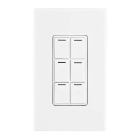
Identifies the specific model of the Control4 Auxiliary Keypad.

Introduction

Product Introduction and Connection

Describes the intended use and connection of the Auxiliary Keypad with a Control4 system.

Box Contents

Included Components List

Lists the items included in the product package for installation.

Compatible Devices

Supported Control4 Devices

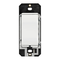
Lists Control4 dimmers, switches, and controllers compatible with the Auxiliary Keypad.

Warnings and Considerations

Electrical Power Safety Precaution

Turn off electrical power before installation or servicing to prevent injury or damage.

Circuit Breaker Requirement

Device must be protected by a 20A maximum circuit breaker.

Grounding Instructions

Ground device per NEC; use ground wire for secure connection to the electrical system.

Licensed Electrician Installation

Installation must be by a licensed electrician per national/local codes.

Consultation for Installation Uncertainty

Consult a qualified electrician if unsure about any part of the instructions.

Wire Type Compatibility

Use only copper or copper-clad wire; aluminum wiring is not approved.

Adherence to Electrical Codes

Install in accordance with all applicable national and local electrical codes.

Warranty and Misuse Clause

Using product differently voids warranty; Control4 not liable for misuse.

Tool Usage and Screw Tightening Caution

Do not use power screwdriver to avoid stripping screws or mechanical issues.

Electronic Device Handling

Handle this electronic device with intricate components with care.

Specifications

Technical Specifications Overview

Provides key technical details including model, power, temperature, and dimensions.

Installation Instructions

Initial Power Disconnection

Turn off local electrical power via circuit breaker or fuse and verify with voltage detector.

Wire Preparation

Strip wire insulation back 5/8 of an inch from the wire end.

Wire Nut Connections

Connect keypad wires to wallbox wires using wire nuts as per configurations.

Yellow Wire Functionality

The yellow wire is for connecting to a compatible Control4 load control device only.

Multi-Gang Faceplate Installation Tip

Attach sub-plate to devices in multi-gang installations before attaching devices to wallbox.

Wallbox Wire Folding

Bend wires in a zigzag pattern to easily fold them into the wallbox.

Keypad Mounting and Fastening

Align keypad to wallbox and fasten with screws, tightening until yoke plate is flush.

Faceplate Attachment

Install Control4 Faceplate or a standard Decora-style faceplate.

Restoring Electrical Power

Turn power back on at the circuit breaker or by replacing the fuse.

Troubleshooting

Keypad Control Issues

Check circuit breaker, wiring, or contact electrician/support if keypad does not control load.

Care and Cleaning

Cleaning Instructions

Do not paint keypad; use a soft damp cloth for cleaning, avoid chemical cleaners.

Regulatory;Safety Information

Regulatory Information Access

Review regulatory information for Control4 products on the Control4 website.

Patent Information

Available Patent Information

Applicable patents are available for review on the Control4 website.

Warranty

Warranty Information Access

For complete warranty information, review the card or visit the Control4 website.

About this Document

Document Identification

Provides the part number and revision date of the installation guide.

Operation and Configuration

Auxiliary Keypad Functionality

Keypad acts as a slave device; describes button functions for load control and fan speed.

Related product manuals