TARATURA CORSA SERVOCOMANDO SOLO PER CORSA DI-
VERSA DA 16,5 mm
• Togliere il coperchio lato opposto alla manopola.
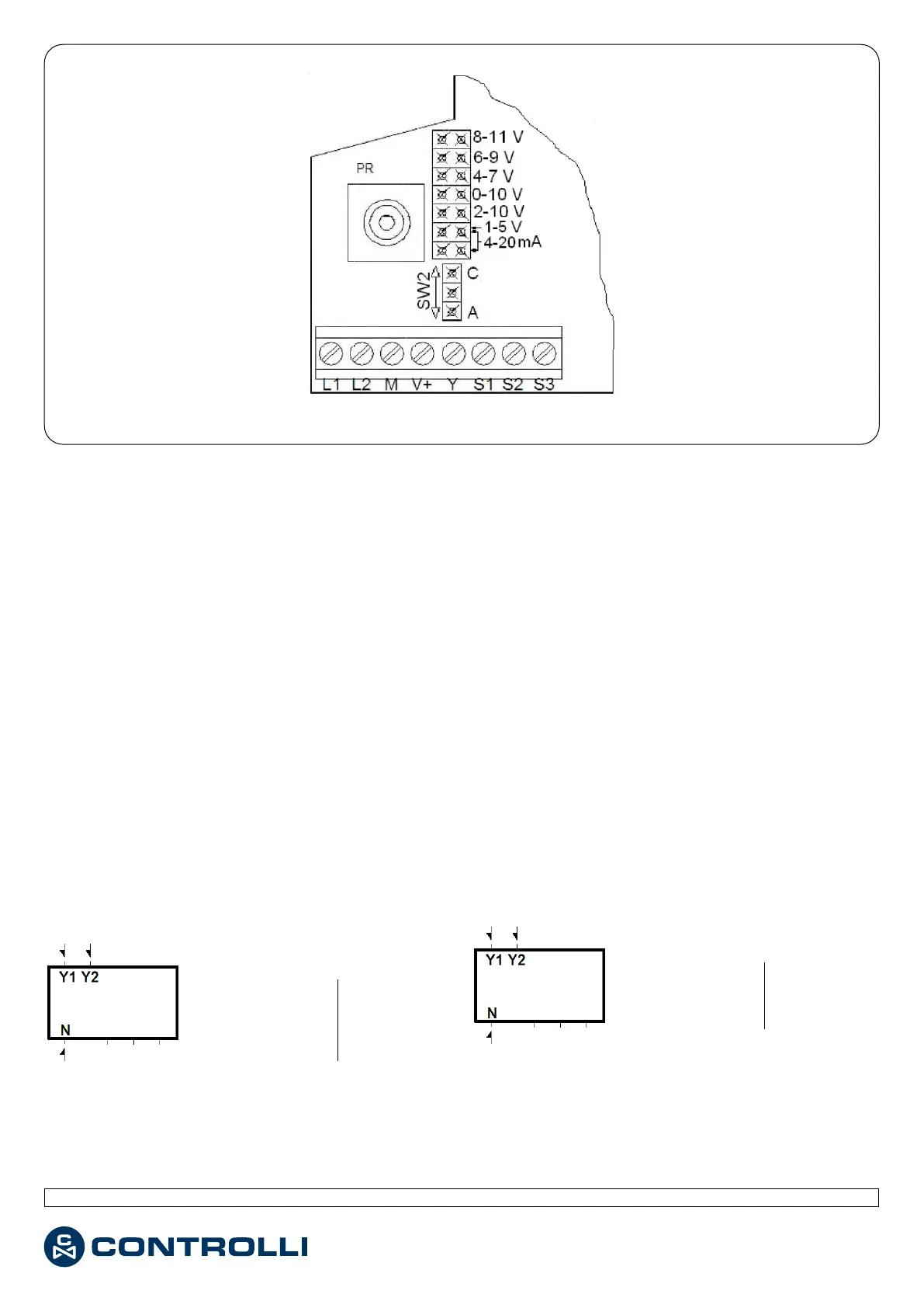
• In caso di MVB52/56, vericare che il ponticello SW2 sia
su A (Fig. 2).
• Alimentare il servocomando tra L1 e L2 con morsetto Y
scollegato.
• Attendere che il servocomando raggiunga il ne corsa
inferiore.
• Collegare il positivo del voltmetro al morsetto S2 e il ne-
gativo al morsetto M.
• Ruotare il trimmer P1 no a leggere 0 V sul voltmetro.
COLLEGAMENTI ELETTRICI
Eseguire i collegamenti come da schema indicato qui di se-
guito ed in conformità alle norme vigenti.
MORSETTIERA
- MVB2. (230 V~)
- MVB46 (24 V~)
LEGENDA
Y1 = Giunto si alza
N = Comune
Comando
(1)
Y2 = Giunto si abbassa
Fig. 2
SOLO PER MVB 36-52-56 / ONLY FOR MVB 36-52-56
ACTUATOR STROKE CALIBRATION ONLY FOR STROKES DIFFER-
ENT FROM 16.5 mm
• Remove the back cover (opposite the knob).
• For MVB52/56 only, make sure that jumper SW2 is in A po-
sition (Fig. 2).
• Supply the actuator between L1 and L2 terminals with Y
terminal disconnected.
• Wait the actuator to reach the lower stroke end.
• Connect the positive of the voltmeter to S2 terminal and
the negative to M.
• Rotate P1 trimmer until the voltmeter indicates 0 V.
ELECTRICAL CONNECTIONS
Perform the electrical connections according to the follow-
ing diagrams and in compliance with existing rules.
TERMINAL BOARD
- MVB2. (230 V~)
- MVB46 (24 V~)
LEGEND
Y1 = Joint up
N = Common Control (1)
Y2 = Joint down
1
a
Emissione / 1
st
Issue rev. a 03/2020 2 DIM001
 Loading...