Controlli S.p.A.
16010 Sant’Olcese (GE)
Tel. 010 73 06 1
Fax. 010 73 06 870/871
www.controlli.eu
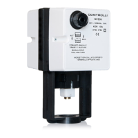
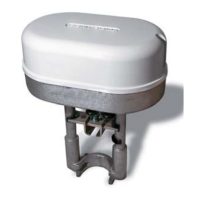
MVH56E/MVHE3K
Valve Actuators
Manual Override
The manual control can be activated only after disconnecting pow-
er supply. To use the manual override, it is necessary to push and
hold down the knob; turn clockwise to move the valve stem down-
wards and counter clockwise to move it upwards (see the picture).
Be careful not to force the manual override when the actuator stroke
end is reached.
MANUFACTURING CHARACTERISTICS
The actuator consists in a die-cast aluminium housing, which includes
the mounting bracket for connection to valve body.
Reduction gears supported by ball bearings. Movement is transmit-
ted to a rack-and-pinion mechanism connected to the valve stem
through a suitable joint.
Internal electronic card with easily accessible terminals for electrical
connections.
End Point Auxiliary Switches (accessory DMVE)
End point switches change over when the valve is fully open or
closed. They are free contacts with 24Vac max voltage on terminals.
End point switches can be utilized to indicate valve stroke end posi-
tions and for relay control of additional plant equipment.
When the actuators are controlled individually or in sequence, it is
possible to use the end switches to toggle when the valve is fully
open or fully closed. The auxiliary switch position according to con-
trol signal (Y) is shown in the table below.
MODEL
FORCE
[N]
POWER
SUPPLY
DESCRIPTION
MVH56E 1500 24Vac/dc Modulating/oating
MVHE3K 3000 24Vac/dc Modulating/oating
APPLICATION AND USE
MVH56E and MVHE3K are exible electro-mechanical actuators for
the control of two-way and three-way globe valves in:
• heating and cooling systems;
• Air Handling Units;
• district heating plants;
• industrial temperature control systems.
MVH56E and MVH3K can be controlled either by a proportional
(modulating) signal or by an increase/decrease (oating) signal.
It is easy to mount and connect the actuators. Direct mounting is
possible to any CONTROLLI anged valve as well as for valves of oth-
er manufacturers (contact our Technical Dept.). The actuators have
a ne resolution (500 steps on the full stroke range) for exacting uid
control and they are able to self-calibrate on a different stroke with-
out the need of any user action (this function is selectable on the
eld via DIP switch).
MVH56E and MVH3K have intelligent behavior and alarm functionali-
ty in case of unexpected operation, feedback of alarms to the user is
provided by two LEDs (GREEN and RED) on the control board.
N.B.: Do not use the actuator if not coupled with its relating valve.
OPERATION
The actuators translate the control signal (modulating or 3 point
oating) from the controller into a valve position. A modern brushless
DC motor in the actuator drive a gear train and a worm gear – screw
jack mechanism convert the motor revolutions into accurate and
repeatable linear movements.
Control Signal
MVH56Ex can be controlled by two main control types.
• 3 point oating ;
• Modulating (or proportional) signal with led selectable range
(e.g., 0-10Vdc, 2-10Vdc, 0-5/2-6Vdc, 5-10/6-10Vdc e 4-20mA.)
Feedback Signal
The actuator utilizes a 2-10V position feedback (look at DIP n. 1 set-
tings).
Calibration
MVH56E and MVHE3K are endowed with an automatic stroke cali-
bration function, but they can be calibrated also manually via DIP n.
7. In factory delivery the auto stroke calibration is enabled; manual
calibration is not necessary unless maintenance is required on the
valve or certain alarm functions are desired.
1
st
Issue 05/2017 DBL466e Page 1