TECHNICAL CHARACTERISTICS
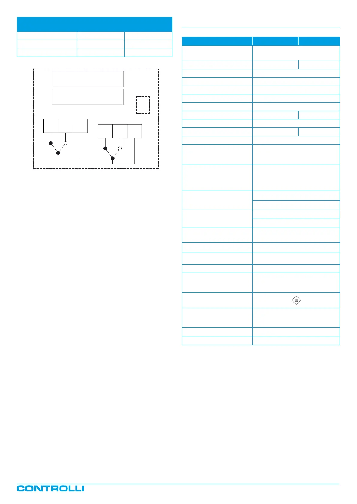
K1 K2 KC1
position
K3 K4 KC2
OPENING RELAY
CLOSING RELAY
DMVE
Diagnostic
The actuator is provided with a self diagnostic algorithm able to
detect faulty conditions:
• stroke out of range 5-60 mm;
• unexpected stall condition (e.g., valve stuck);
• missing expected stall condition(e.g., link loose);
• voltage supply out of range.
These faulty conditions are signalled via the GREEN and RED LED on
the electronic board blinking accordingly (see “Diagnostic – Alarm
Function Table”).
Control signal (Y)
Relay
KC1
Relay
KC2
0-0,5Vdc KC1 to K2 KC2 to K3
0,5-9,5Vdc KC1 to K1 KC2 to K3
9,5-10Vdc KC1 to K1 KC2 to K4
MVH56E MVHE3K
Supply voltage L1 Ln
AC: 24Vac ±20% 50-60Hz
DC:22-30Vdc (Reference Ln)
Power consumption 12VA/5.2W 17VA/8.5W
Modulating 5-15mm 15s
Modulating 15-25mm 25s
Modulating 25-40mm 35s
Modulating 40-60mm 50s
Floating 60s
Transformer Size [VA] 50 60
Stroke 5-60mm
Force [N] 1500 3000
Duty cycle max 50%/60 minutes
Analogue input Y M
Voltage 0-10V - impedance > 100kΩ
(range: 0-10 2-10 0-5/2-6 5-10/6-10)
500Ω (range 4-20mA)
Digital inputs Y1-Y2
Connection to L1 or Ln when
powered in AC
Connection to Ln only when
powered in DC
Output V+
Voltage 16Vdc ± 0,5V
Max Load 25mA,
Output U
Voltage 2-10Vdc (0-100%)
Max Load 2mA
Cable glandes
plastic punchable, replaceable by
PG13,5 compression glands
Type of movement linear
Ambient temperature Operation and storage -10/+50°C
Ambient Humidity max 90% RH
Protection degree
IP55 DIN40050 (IEC 529) for highly
polluted environments according
to IEC 730-1 (93)/6,5,3
Insulation class
Standard
Emission/Immunity EMC 2004/108/
CE according to EN 61326-1:2006
standard
Weight [kg] 4
Dimensions [mm] Refer to the picture on page x
1
st
Issue 05/2017 DBL466e Page 2