system.
• The number
of
wires
in
your system can be as few as two (for heat only
systems), as many as eight, or any number
in
between. If you follow the
labeling procedures correctly, you do not have to
be
concerned about how
many wires there are.
• There is often no terminal marking on the existing thermostat of two wire,
heat only systems. Just connect either
of
the wires to the
RH
terminal, then
connect the other wire to
theW
terminal to complete the circuit.
• IMPORTANT! BEFORE DISCONNECTING ANY WIRES, APPLY THE
SELFADHESIVE LABELS PROVIDED TO THE WIRE AS SHOWN
IN
TABLE A BELOW. (For example, attach the label marked W to the wire that
toes to the W or H terminal
on
your existing thermostat.) IGNORE THE
COLOR OF THE WIRES since these do not always comply with the
standard.
• After labeling wires, disconnect them from the existing thermostat.
• Remove existing wall plate.
To
make sure wires do not fall back into wall
opening,
you
may want to tape them to the wall.
•
If
hole
in
wall is larger than necessary for wires, seal this hole with
insulating material so that no hot or cold air can enter the back
of
the
thermostat from the wall. This air could cause a false thermostat reading.
If
the
code
letter
on
your
existing
Thermostat
is
RH,R.VRor4
•
•
•
ReverslngVatl/oopcralmginKcatmode
~~~~-~~-PUIIlpsONLY)
,
RC,VC
-------
Volll'""'
Table A
then
mark
the
wire
with
label
shown
/S)
. LC"_
..
~
...
'~""v'''"'""""""'t
~
(S~I<!_~~"
Hea_t""':'P"_
~-l-~)
-
-~-
~~
-----------------
•
•
•
•
.
~
.
-~------------~--
Y,Y1,CorM
AirCoodrtioningCompressor
~~SiagaHealPIJmp
~
Compressor
~~:~
~
1
~-~=---
-.
(Sj)gl~~-~~~~~~!
__
L!f:_
~
.~
•
•
and
connect
to
thermostat
terminal
shown
NOTE: Do not connect a "Common" wire (sometimes
labeled "C'? to
any
terminal on this thermostat.
Tape
up the wire
and
do not
use. This wire provides electricity to non-battery powered thermostats.
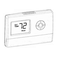
Mount
wallplate and Thermostat
• Remove the wallplate from your thermostat. See Figure
2.
Figure
2
• Position wallplate on wall and pull existing wires through large opening.
Then level for appearance. Mark holes for plastic anchors provided, if
your existing holes do not line up with those
on
the wallplate.
• Drill holes with 3/16" bit and gently tap anchors into the holes until flush
with wall.
• Reposition wallplate to wall, pulling wires through large opening. Insert
mounting screws provided into wall anchor and tighten. See Figure
3.
Figure
3
NOTE: 5- Wire Systems
If your thermostat has one wire marked R or
Rh
(2,
3,
or 4-wire system),
then leave the jumper wire between the
Rh
and Rc terminals
on
the
wall plate. Otherwise, if you have separate
Rh
and Rc wires (5-wire system),
then remove the jumper wire between the
Rh
and Rc terminals.
Connect
Wires and
Mount
Thermostat
to
wallplate
• Match and connect the labeled wires to the appropriate coded terminal
screws
on
the wallplate. (See Figure
4,
5.) Ignore any wires which may
be
present, but which were note connected to the old thermostat.
{[Rhi
Figure 4
Figure 5
• Refer to the Wiring Diagrams below to be sure your system is wired
correctly.
•
If
your system is a single stage heat pump and uses
an
0 or B wire, you
must move the System Selector switch inside the thermostat to the Heat
Pump position.
If you have a normal furnace or electric system, leave the
switch
in
the Standard position. Refer to the System Selector section
on
the
back for more information on this switch .
• Be sure to tighten the terminal screws securely, otherwise a loose wire
could cause operational problems with your system or thermostat.
• Push excess wire back into the hole to prevent interference when
installing the thermostat to the wallplate.
• Make sure the System
Switch is set to
OFF,
and the Fan Switch is set to
AUTO.
•Insert
the tabs
on
top
of
the thermostat body into the slots at the top of the
wallplate. Press the bottom
of
the thermostat body into the snap
on
the
bottom
of
the wallplate. Refer to Figure
2.
(NOTE:
Do
not force the
thermostat onto the wallplate, as the terminal pins may
be
damaged.
If
it
does not snap properly, the thermostat may not work.)
• Insert the two AA size alkaline batteries, observing the polarity marked
inside the battery compartment.
• Switch on the main power at the panel or furnace.
Wiring Diagrams
,
I·-
i -
r·1
i-Wi31Tpl3t9-
Tarmlnals
i
~
1
-waliPiiiie
Tenninals
iWalli>klte
Tenninals
l.
w
..
a.llplliie
Terminals
!"
1•'-~_]
4\\lire
HeaVCool
,._
(vl
l
I
Jumpar
5-Wire
HeaVCool
System
\G.'
(W)
})
iW'J
·
-~t~LrL~~r~
=L~~v~
IRe">'lJvafleT_.
1
L<:<>o~_jl~flll'f--J
-
rf\__
J
~ngle·Stage
Heat
PUmp
System
Jumper
-~
\.R)
<ill
'r!
;;;v
<i<o>
i l
~Heat10R]Cooi
i !
~
IMOOe
- - L I L
i
Fan
!
rcomPressoTl
1
Reversing
I
1Relay
I
[Cont.Qctor_~
j
IV.alve
i .
··1····
....
I
.
..
--
2·\\lire
Heat
Only
systEm
Jumper
r~~
)=leafReJa101
[yaw.T_
3-WireHeatOnlySystem
Jumper
'wa1ipiaie
I
Terminals
i
(R)
®
Wil
i)
I
•
~.J·.'r
. .
c......
·r·
1
:,.1·--
~
.....
;.day.
<.~1
)(
__
I
-r------
_
[~elay
[valve
"
· .
l_L_L_
3-Wire
Cool
Only
System
systEm
I
STD
sek>:tor
1
I .
HP
systEm
Selector
systEm
Seledor
systEm
Sek>:tor
System
Seledor
systEm
Seledor
STD
HP
STD
HP
STD
HP
STD
HP
STD
HP
X-No Connection
Selector
Switches
In
order for this thermostat to control your system, the system type must
be
specified by the selector switches on the printed circuit board inside the
thermostat. There is also a selector switch for your choice of Fahrenheit or
Celsius temperature display. See figure
6.
• Heating System Selector
(HG-
HE
switch)
The factory position for this switch is
in
the "HG" position. Leave it
in
this
position if you have a gas furnace or
an
oil burner. If you have
an
electric
furnace, test to see
whether· the Heat and Fan come on as expected after
installation.
If the Fan operation is normal, leave it
in
the "HG" position. If
the Fan does not come on within a minute
of
the thermostat calling for
heating, change the switch position to
"HE". The system selector has no
effect
in
the cooling mode.
NOTE: "HG" position is for gas and most other systems. "HE" position
is
for
certain electric systems having a fan relay.
• System Selector
(STANDARD-
HEAT PUMP switch)
The factory position for this switch is
in
the STD position. Leave it
in
this
position
if
you have ANY system that uses gas, oil, electric, or hot water
heating.
If you have a single-stage Heat Pump (no auxiliary or emergency
heat source), then slide the switch to the
HP
position.
Be
sure the reversing
valve wire is connected to the correct terminal for your heat pump
(RciO) or
(Rh/B).
•
'F
I ·c selector (Fahrenheit I Celsius)
Your thermostat is set for
'F
mode from the factory.
In
order to change to ·c
mode, slide the switch to ·c and hold any key about 2 seconds without the
battery, then place the battery again.
NOTE: Unless press any key about 2 seconds without the battery, then
place the battery again.
0
0
Figure 6
TROUBLESHOOTING
Problem
Solution
No Display
1.
Check battery connections and batteries.
2.
Move the battery out and wait for about 1
minutes then Replace Batteries
..
Entire
Display
1.
Replace Batteries.
Dims.
Auto Fan Does Not 1. Move HGIHE selector to correct position.
Turn
On Properly.
Heating or Cooling
1.
Check that the function switch is
in
the correct
Does Not Go
On
or
position ("HEAT" or "COOL").
Off.
2.
There may
be
as much as 4-mintue delay
before the system turns
On
- wait and check.
(Compressor protection delay.)
3.
Check your circuit breakers and switches to
ensure there is power to the system.
4.
Replace batteries.
5.
Make sure your furnace blower door is closed
properly.
6.
If
your non-heat pump system only uses
4-wires, be sure the jumper wire is installed
between the Rh/B and
Rc/0
terminals.
7.
Check the position
of
the Reversing Valve
selector switch: Standard or Heat Pump.
8.
If you have single-stage heat pump, be sure
the jumper wire is installed between the
Y and
W terminals.
Erratic Display
1.
Move the battery out hold any key then place
the battery again. Then reprogram.
If unit continues to
1.
Replace unit.
operate
in
the Off
position.
Thermostat
1.
Replace unit.
permanently reads
"HI",
"LO",
or
"E1",
"E2".
-
!
I
I
 Loading...