Digital Thermostat
Owners Manual
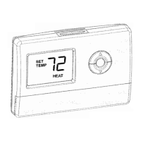
Modei:CT72
Your new thermostat will provide years
of
reliable service. Using this
digital thermostat will provide more uniform comfort
in
your home through
the seasons. Thank you for buying the product!
Please read this manual for complete instructions on installing
and
operating your thermostat. If you require further assistance, please feel
free to contact
us.
IMPORTANT INFORMATION
1. This
thermostat
is
designed
to
work
on
the
following
systems:
• Gas - Standing Pilot
•
Gas-
Electronic Ignition
•
Gas - Fired Boilers
•
Gas-
Milivolt Systems
•
Oil
- Fired Boilers
• Oil
- Fired Furnace
• Single Stage Heat Pumps - with no
auxiliary heat
• Electric Furnace
• Electric Air Conditioning
This thermostat
will NOT control multistage heat pumps or
11
0/220V
baseboard electric heating systems.
2. Temperature Range
This thermostat can be set between
45"F and
95"F.
However, it will display
room temperatures from 30"F to
99"F.
"HI" will
be
displayed
if
the
temperature
is
higher than
99"F,
and "LO" will
be
displayed if the
temperature
is
lower than
30"F.
This thermostat will automatically cutoff
in
Heat mode if the temperature
rises above
72"F,
and automatically cutoff in Cool mode if the temperature
drops
below
72"F.
3.
Compressor
Protection
This thermostat provides a 4 minute
delay after shutting off the compressor
before it can be restarted. This feature
will prevent damage to your
compressor caused by rapid
cycling. It does not prevent a rapid
compressor restart due to short power outages.
4. Battery Warning
Two
fresh
AA
alkaline batteries should provide well about one year
of
service. However, when the batteries become drained the Low Battery
Indicator will flash on the display. When this message occurs, install new
alkaline batteries.
You
have approximately 1 minute to change the batteries
and keep the thermostat's settings.
Once the batteries have become
too
low to ensure proper operation, your system will
be
turned off, and the
display will be cleared except for flashing Low Battery Indicator on the LCD
display.
CAUTION:
When only the battery icon flashes
on
the display, the
thermostat
is
shut down, and your system will no longer operate.
In
this
condition, there is
no
temperature control
of
your dwelling.
NOTE:
The
backlight will not function when
the
thermostat
is
in
low battery
condition.
NOTE:
If
you plan
to
be away from the premises over 30 days,
we
recommend that you replace the old batteries with new alkaline batteries
prior
to
leaving.
5.Power
supply
The thermostat shall
be
powered by 24
VAG
and
with batteries as backup.
FEATURES
Structure
of
thermostat and explanation for the keypads
light:
Backlight display automatically
with
each key press
for
easy
viewing.
Filter Change
lndicator:Fiashes--
when filter needs
to be checked.
LCD
DiSplay:
Shows Room
Temperature,Set
1
.-----------
Temperature,and
.-------------bhh,
~.==~==
other feature -
information as
required.
Front Door:
Low
Battery Indicator. Flashes when
batteries need to be replaced.
Filter Key:
Resets
the
filter
change
counter to zero.
Up
and
Down
Keys:
Keys
for changing
the Temperature
setting. Also used
for adjusting the
Span.
Fan Switch: Fan
- switch for Automatfc
or Continuous fan
operation.
System switch:
selector switch
for
Heat,Cool,and Off.
Cover
keys Open with
one
finger from left
or
right.
OPERATION
Start-up
The LCD will show the factory default display
of
70"F when batteries are first installed,.
The temperature will update after a few
seconds.
System Selector Switch
TEMP
flf
IU
system
CLcl2)
cool off heat
The System Selector switch
on
the front of the
thermostat determines the operating mode of the
thermostat.
You
may select COOL,
OFF,
HEAT.
NOTE: Anytime you install or remove the thermostat from the wallplate,
slide
the System Selector to the OFF position to prevent the possibility of a
rapid system
On
-
OFF.
Fan Switch
fan
([oJ)
on
auto
The
Fan
switch should normally
be
located
in
the AUTO
position. The
Fan
will be turned on along with normal
operation
of
your system.
In
a normal gas or oil furnace,
the Fan
will
be
turned on by your furnace after its
warm-up delay. For
electric heat, air conditioning, and heat pump operation,
the Fan
will turn on with the system.
To
run
the
Fan
on
continuously, slide the
Fan
switch to the
ON
position.
Review Current Set Temperature
• Press either the up or down key once to see the Set Temperature.
The factory default is
68"F when started with the System Switch Off or Heat,
and
78"F when started with the System Switch on Cool.
Setting New Temperature
• Press either the up or down once and
display the set temperature.
• Press either
up
or down again to change to
your desired
Set Temperature. Hold the key
down for over 2 seconds to fast advance the
Set Temperature.
I-
SET
5
n
TEMPO
u
The display will return to the normal room temperature after the keys have
been
released for 5 seconds.
Filter
Monitor
The thermostat counts the number
of
hours
your system's
filter has been
in
use.
To
maximize your system's performance and
energy efficiency, change or
clean your filter
regularly. When the total system
run
time for
~~-~FILTER
/;11\'-
i
TEMP
tC
I:J
COOL
heat and cool reaches 400 hours, the Filter Change Indicator will flash as a
reminder to check your system's filter.
After changing or cleaning the system filter, press and hold the Filter key
for 3 seconds. The
display will blink,
and
the counter will be reset to zero.
Note:
Pressing the Filter key at any time for less than 3 seconds will cause
the Filter Change
Indicator to appear
on
the LCD. This
is
only to confirm
key operation,
and
the counter
is
not affected unless the key
is
held for
greater than 3 seconds.
SPAN
Setting
Your thermostat
is
set at the factory to cycle at
2"
F above and below the set
temperature.
(Span
= 2) This setting has been designed to provide a
comfortable room temperature under most all conditions. However,
if
you
find your system
cycling too fast or too
slow,
then the Span can
be
adjusted
to modify the
cycle time.
~
'\::£}
• Press
and
hold BOTH up and down keys for three
seconds.
SPAN
will be displayed on the LCD.
• Press up to raise the
Span
to
3.
This setting
INCREASES
to
cycle time
by
allowing your system
to run
LONGER.
• Press
down to lower the Span to
1.
This setting
DECREASES the cycle time by causing your
system to
run
SHORTER.
The Span settings remain the same for both HEAT and COOL,
and
can be
changed
in
any System Switch position.
When batteries are installed
in
the thermostat, the Span is reset back to
setting
2.
Backlighting
Your thermostat has
an
electroluminescent lamp that backlights the display
for easy viewing in the dark.
When any key is pressed, the display is
illuminated.
The display will remain illuminated for 7 seconds after the last key is
pressed. This
allows the light to stay on if you need to operate several
keys.
Note:
If
the
thermostat is
in
Low Battery warning condition, the backlight
will not operate. Replace with 2 new
AA
alkaline batteries to restore the
Backlight function.
Low
Battery Warning
Your thermostat has a two-stage lower
battery warning system. When the
batteries are first detected to
be
weak, the
first stage low battery warning is indicated
by
battery symbol flashing on the
LCD
display. At your earliest convenience,
you
------~
~~~p6-l~Q~~~
.
....-'//IJ
need to replace the batteries with 2 new
AA
alkaline batteries. When the
batteries become too weak for
normal operation, the thermostat enters the
second stage
low battery warning which shuts down the
thermostat.
In
this condition, battery symbol flashes alone
on
the display, and the
thermostat
will turn your system off. Your system will remain shut-off until
the batteries are replaced.
Note:
The
thermostat will still keep
the
current Set Temperature and Filter
run time
in
memory until new batteries are installed. After confirming that
new batteries have been inserted,
the
thermostat will return
to
normal
operating.
Error
Mod~
If the thermostat is unable to control your
system due to an unexpected battery
problem, the thermostat will enter Error
Mode.
In
this condition, the thermostat
\flashes "E1"or "E2" on the
LCD
display,
and
,shuts off your system.
~·-
-1
.-
I
Ct
--
j
!To
correct this problem, replace the batteries with 2 new
AA
alkaline
batteries, even if you have recently
replaced them. Next, Move the battery out
hold any key then place the battery again.
You
will need to reprogram your thermostat
and confirm
normal operation. If Error
Mode returns, please
call
us
for further
information
Sensor Error
Auto
Cut
Off
information
Svstem switch Error
Your thermostat will automatically cutoff
in
Heat mode if the room
temperature rises above
72"F.
It will cutoff in Cool mode if the room
temperature drops
below
72"F.
:Note that
if
your system has malfunctioned and no longer responds to
thermostat
controls, the Auto Cut-Off will have no effect.
INSTALLATION
What
You Need
This thermostat
includes two #8 slotted screws and two wall anchors for
mounting.
To
install your thermostat, you should have the following tools
and
materials.
• Slotted
Screwdriver(s)
• Small Philips screwdriver
• Hammer
• Electric drill and 3/16" bit
•
Two
1.5V
(AA)
size alkaline batteries (included)
Remove Old Thermostat
CAUTION: Do
not
remove
any
wiring
from
existing
thermostat
before
reading
the
instructions
carefully. Wires
must
be
labeled
prior
to
;removal.
INPORTANT! Turn
off
the
power
to the furnace
at
the
main
power
panel
or
at
the furnace.
IRemove existing thermostat cover
and
thermostat. Some thermostats will
!have screws
or
other locking devices that must first be removed. Once the
lwall mounting plate is exposed, look for wires. If wires are not visible, they
!may
be
connected to the back
of
the wall plate. Again, look for screws, tabs,
etc.
Some models have doors that open to expose wires
and
mounting
screws.
See Figure
1.
. Typical Home Thermostats
(f)~~l
(0
~
Wall mounting Plate Thermostat Cover
~~~~tJ
Wall
mounting Plate Thermostat
Cover
Figure 1
Wiring Labeling
• Each wire coming from the wall to the existing thermostat
is
connected to
a
terminal point
on
that thermostat. Each
of
these terminal points is usually
marked with a code latter
as
shown
in
Table A below.
•
Note that this thermostat has multiple function terminals that allow
Single-Stage
Heat Pump capability. Standard systems use:
Rh,
Rc,
G,
Y,
W.
[Single-Stage Heat Pumps use:
R,
Y,
G,
and 0 or B.] Table A below shows
;the multiple functions
of
the terminals. Use the terminals that match your