10
1/8”
4”
1/8”
4”
20
5”
5”
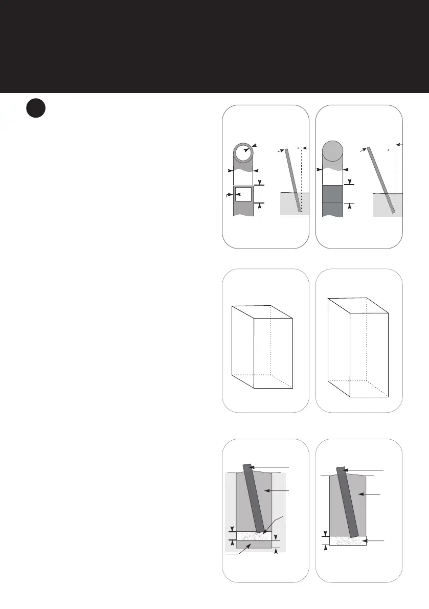
INSTALLING ADDITIONAL SUPPORTS
A. Steel Posts: If additional posts are required,
galvanized steel posts are suitable and are
available from your local hardware outlet.
Steel posts can be cut to predetermined
lengths and painted to a color of your
choosing. We recommend the use of a
minimum 4″ diameter round or 4″ x 4″ square
galvanized steel posts with at least 1/8”
thickness. An angle of at least 10 degrees is
also recommended for steel posts sloping
away from the center of the shade sail (Fig. 3).
B. Timber Posts: We recommend the use of a
minimum of 5″ diameter treated timber posts.
An angle of at least 20 degrees is recommended
for timber posts sloping away from the center
of the shade sail. Consult your local hardware
outlet for the appropriate class of treated pine or
hardwood timber for your region (Fig. 4).
C. Footings: Dig footings with the center of the
hole as the approximate location point of the
shade sail. Dig footing holes as illustrated.
Consult your local hardware outlet for the
appropriate design of footing. For shade sails
with sides less than 13′, dig footing holes 15.5″ x
15.5″ square and 31″ deep (Fig. 5). For shade sails
with sides more than 13’, dig footing holes 15.5″ x
15.5″ square and 47″ deep (Fig. 6).
D. Concreting: Mix concrete in line with
manufacturer’s instructions. It is not
recommended to use rapid set concrete. Your
local hardware outlet will be able to give you any
special advice you may need for your conditions.
E. So Ground: Pour a 4″ depth of concrete at the
bottom of the hole to provide a solid pad. Allow
to set. Add gravel, post and the required amount
of concrete. Temporarily brace the posts on
angle (Fig. 7).
F. Firm Ground: Lay a 4″ depth of ¾” diameter
gravel at the base of the post. Add concrete and
brace post on angle (Fig. 8).
G. Pour concrete to the top of the footing holes
ensuring it is packed well. Crown the concrete
around the post so that the sloping away from
the post will drain water away. Ensure water
will not pool at the base of the post as it may
cause deterioration of the post. You may want
to allow space at the top of the footing if you are
replacing with dirt and grass. Allow poles to set
in concrete for a minimum of 48 hours or time
as required by the manufacturer’s instructions.
Brace if required to ensure proper angle.
3
15.5”
15.5”
15.5”
15.5”
31”
Fig. 5
Fig. 8
Fig. 3 Fig. 4
Fig. 6
Fig. 7
4”
3/4”
diam.
gravel
Concrete
footing
Post
Concrete
Pad
4”
4”
Concrete
footing
Post
3/4”
diam.
gravel
 Loading...