Revised: 10/05/2008 Printed: 22/04/2009
3
INSTALLATION INSTRUCTIONS (FREESTANDING MODELS ONLY)
Select the position of your heater carefully, taking into consideration all combustible materials in the
roof; eg. ceiling joists, roof trusses, etc.
Determine flue location through the ceiling:
Position the hearth correctly, then place the heater on the hearth so that the flue spigot on the heater
is correctly aligned with the flue location from the ceiling.
This heater has been tested and approved to AS 2918:1990 using a
Shamic
ShamicShamic
Shamic
Flue Kit.
Flue installation instructions are included with all
Shamic
ShamicShamic
Shamic
Flue Kits.
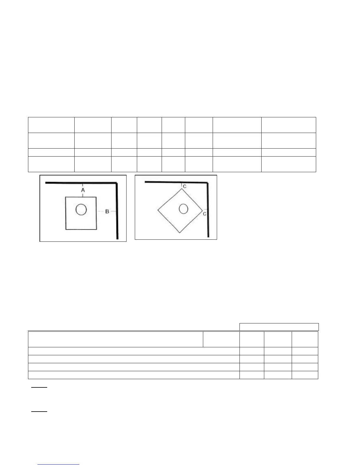
Clearance to combustible surfaces:
Freestanding Models:
Minimum
distance mm
Reference
Symbol
CCF3 MIDI MIDI
BAY
CMF2 BAYWINDOW
ASHPAN
BAYWINDOW
ASHBED
Standard
Installation
A 125 175 160 100 50 100
B 375 375 350 350 350 375
Corner
Installation
C 175 100 175 75 125 125
Standard Installation Corner Installation
INSTALLATION OF FIRE PLACE INSERT MODELS ONLY
The heater must only be installed in either a sound concrete or masonry fireplace, connected to a
chimney, both of which must be inspected for soundness and thoroughly cleaned before the heater is
installed, or the
Shamic
Shamic Shamic
Shamic
tested and approved Zero Clearance Heater Casing unit in conjunction with a
triple skin flue system. After removing the packaging, slide the heater into the fireplace opening. The
internal hearth must be level with, or higher than the external hearth. A flue system must be
connected to the heater, providing free and effective discharge of combustion by-products outside the
building and any enclosed or confined space.
Dimensions in mm
Minimum distance: mm Models: CCI-3
CMI
BWIA
From top edge of hot air outlet to underside of mantle piece / shelf 600 450 425
From outer vertical edges of heater fascia to mantle piece uprights 20 50 75
Floor / hearth in front of heater from door sealing edge (fuel opening) 500 300 425
Floor / hearth in front of heater from either side of fire box opening 200 200 200
Note: The fireplace cavity must be sufficient to accommodate the external firebox dimension with a
recommended minimum clearance of 25 mm all around.
The power cord may be relocated from the right-hand front side of the heater to the left-hand side.
Note: This procedure must only be carried out by a licensed electrical contractor.