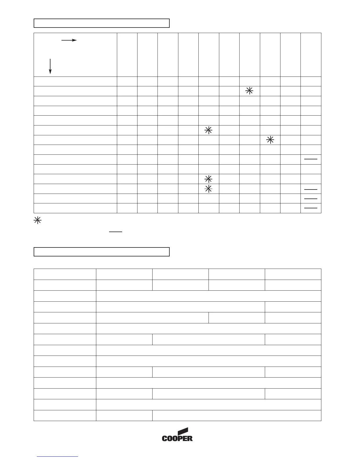
Panel fire/fault indicators
Specification
9
Normal condition
--------
Zone wiring open/short
--------
Zone disabled
--------
Sounder cct. disabled
--------
Sounder and zone cct. disabled
--------
Power supply fault
--------
Sounder circuit open/short
--------
Panel in test
--------
System fault
Panel button pressed
--------
Battery open circuit/reverse polarity
--------
Battery high/low voltage
Fire
Evacuation
General fault
Fire
Disable
Power On
Charger fault
System fault
Disable/Fault zone
Disable/Fault
counder cct
Test
Buzzer
Panel type
1 Zone 2 Zone 4 Zone 8 Zone
Detection zones 1 2 4 8
Detectors per zone 32
Alarm lines 2 4
Max. alarm line load 300mA total (shared) 800mA total (shared)
500mA per alarm line
2A total
Fire/Fault relay Ye s
Aux. DC output No Special order 24v DC Fused 30mA
Mains input voltage 230v AC - 10% + 15%
System operating voltage 24v DC
Battery 1 x 12v/2.1Ah 1 x 12v/3.2Ah 2 x 12v/3.2Ah
Recharge period 24 hours
Repeater output No Special order Ye s
Environmental rating IP30. -5°C to 40°C Humidity 75% max (NC)
Dimensions 260(w) x 212(h) x 72(d) 332(w) x 270(h) x 90(d)
LED flashing
LED illuminated
Internal buzzer intermittent
Internal buzzer steady
--------
Indication
Situation
 Loading...