Before You Begin Menvier40/100
Page 4
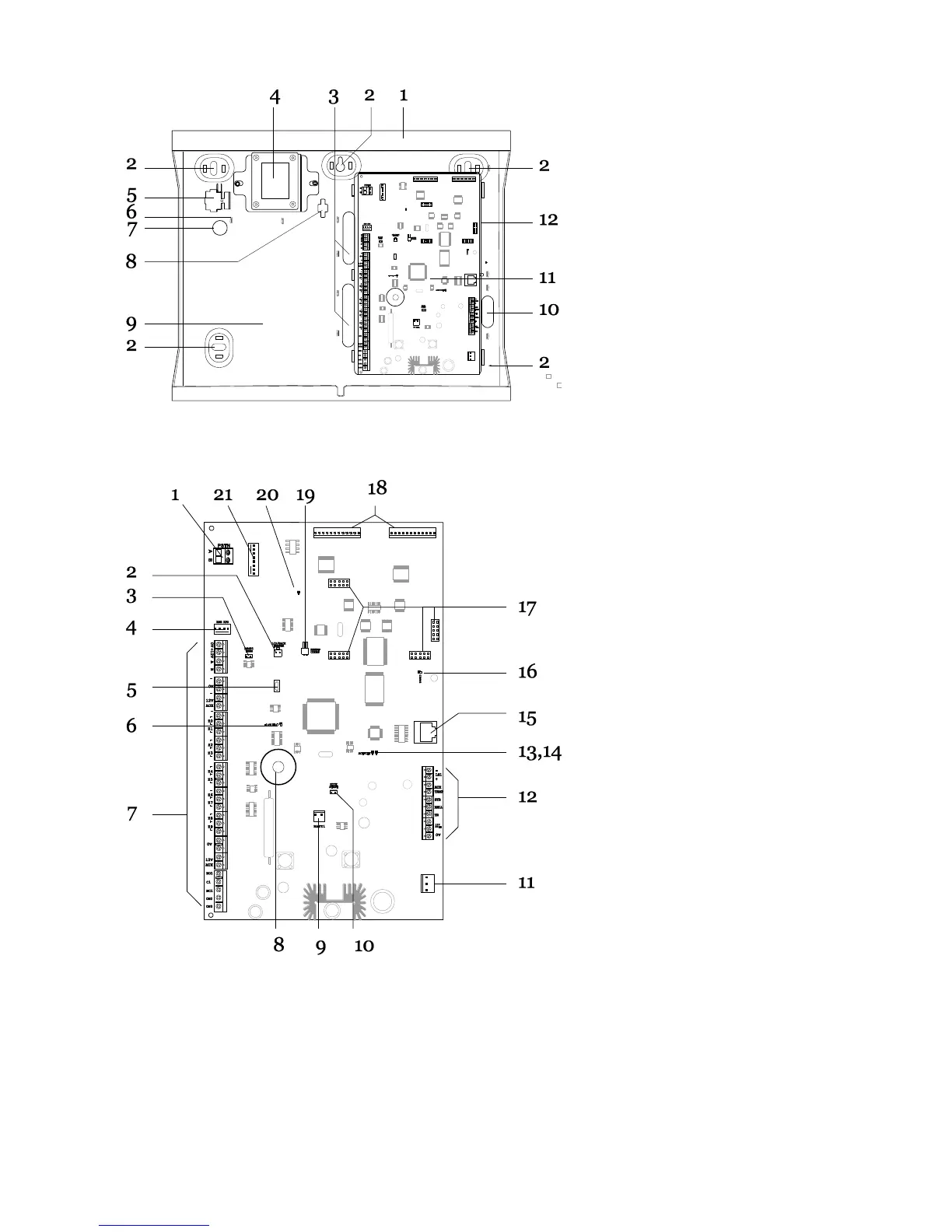
1. Case back.
2. Fixing holes.
3. Cable entry holes for detector
and keypad wiring.
4. Transformer.
5. Fused mains connector.
6. Mains cable anchor point.
7. Cable entry hole for mains
supply.
8. Hole for back tamper fitting.
9. Space for batteries (one 17Ah).
10. Cable entry holes for
loudspeakers, siren/strobes and
communicators.
11. Printed circuit board (PCB).
12. Plastic PCB tray.
1. PSTN Connector for on board
communicator.
2. Lid tamper connector.
3. RS485 terminator.
4. Engineering keypad connector.
5. USB socket (Mini B).
6. Heartbeat LED.
7. Zone-, output-, and Aux power
connectors.
8. Sounder for locating panel.
9. Battery connector.
10. Kickstart pins.
11. 20Vac connector.
12. Connectors for loudspeakers,
sirens and strobes
13. Ethernet activity.
14. Ethernet speed.
15. Ethernet socket.
16. Comms activity LED.
17. Sockets for plug on module.
18. Plug by output connectors.
19. Reset Codes pins.
20. Onboard communicator activity
LED.
21. ADSL filter connector.
Control Unit Printed Circuit Board
 Loading...