QD3 Quik-Drive Voltage Regulator Tap-Changer Manual
50
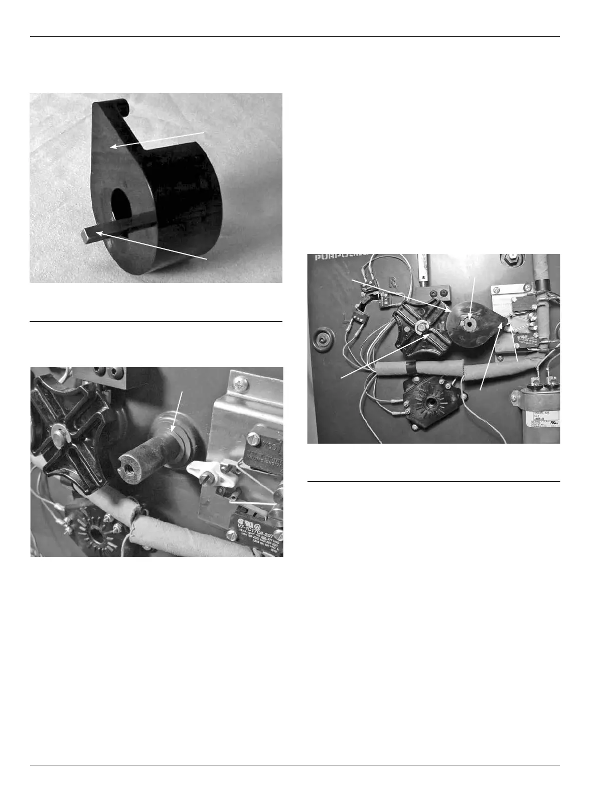
4. Remove the Sprocket Key from the PI Cam slot. (See
Figure 143.)
Figure 143.
PI cam and sprocket key.
PI Cam
Sprocket Key
5. Remove the PI Cam Wave Washer that is located
between the PI Cam and the front surface of the tap
changer. (See Figure 144.)
Wave Washer
Figure 144.
PI cam wave washers.
PI Cam Assembly
6. Place the new PI Cam wave washer over the shaft.
(See Figure 145.)
7. Place either the new sprocket key or the original
sprocket key in the slot of the new PI Cam.
8. Align the new PI Cam up so that the sprocket key
matches up with the key slot in the shaft. Insert the
sprocket key in the slot between the shaft and the PI
Cam.
9. Rotate the PI Cam point so it is pointing at the actuator
located on the holding switch. (See Figure 145.) The
large radius end of the cam should be match with the
radius arc of the PT Drive Geneva Gear. (See Figure
145.)
10. Place the washer over the PI Cam fastening screw.
11. Place a drop of 243 Locktite on to the screw threads.
Place the screw into the tapped hole on the shaft
and hold the PI Drive Cam so it does not rotate while
tighten with a Phillips Screw Driver.
Large Cam Radius
Figure 145.
PI cam assembly.
PI Drive
Geneva Gear
Sprocket
Holding
Switch
Cam Point