QD3 Quik-Drive Voltage Regulator Tap-Changer Manual
74
INSTRUCTIONS
Removing Holding Switch
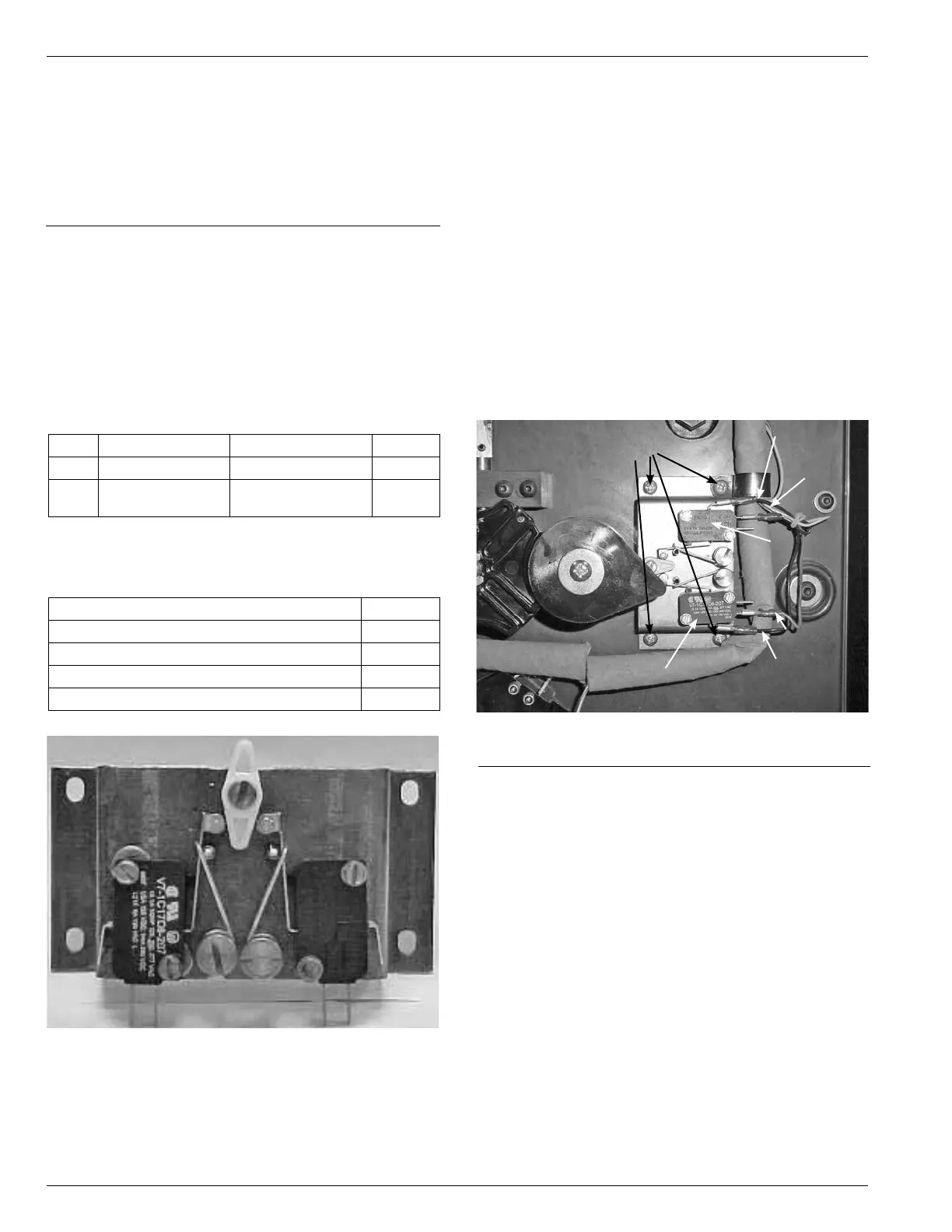
1. Using a pair of pliers remove the four leads form the
holding switch assembly. Facing the holding switch
you will nd the wires by color. (See Figure 232.)
Top Micro Switch
Black wire on top terminal post (com post)
Blue wire on center terminal post (No. 2 post)
Bottom terminal post, vacant (No. 3 post)
Bottom Micro Switch
Top terminal post, vacant (No. 3 post)
Red wire on center terminal post (No. 2 post)
Black wire on bottom terminal post (com post)
Figure 232.
Holding switch connections.
Mounting
Screws
Black Wire
Blue Wire
Top Switch
Red Wire
Black Wire
Bottom Switch
2. Use either a Phillips screwdriver, standard at blade
screwdriver or an Allen wrench and remove the four
screws fasten the holding switch in place. Earlier Quik
Drive tapchangers were built using pan head and
Phillip screws. (See Figure 232.)
QD3/T350 QUICK DRIVE
HOLDING SWITCH ASSEMBLY
KIT
Kit Number 574074B04
GENERAL
The purpose of this installation instruction is for replacing
the holding switch on a QD3 Quik Drive Tapchanger.
TABLE 25
Parts Supplied
Item Part Number Description Qty
1 2240794B04 Holding Switch 1
2 0800073409Z #832 Machine
Screw
4
TABLE 26
Tools Required
Description Qty
Pliers 1
Phillips Screwdriver 1
Standard Flat Blade Screwdriver 1
Allen Wrench 9/64 inch 1
Figure 231.
Kit part.