S225-12-1
75
!
SAFETY
FOR LIFE
Installation of Holding Switch
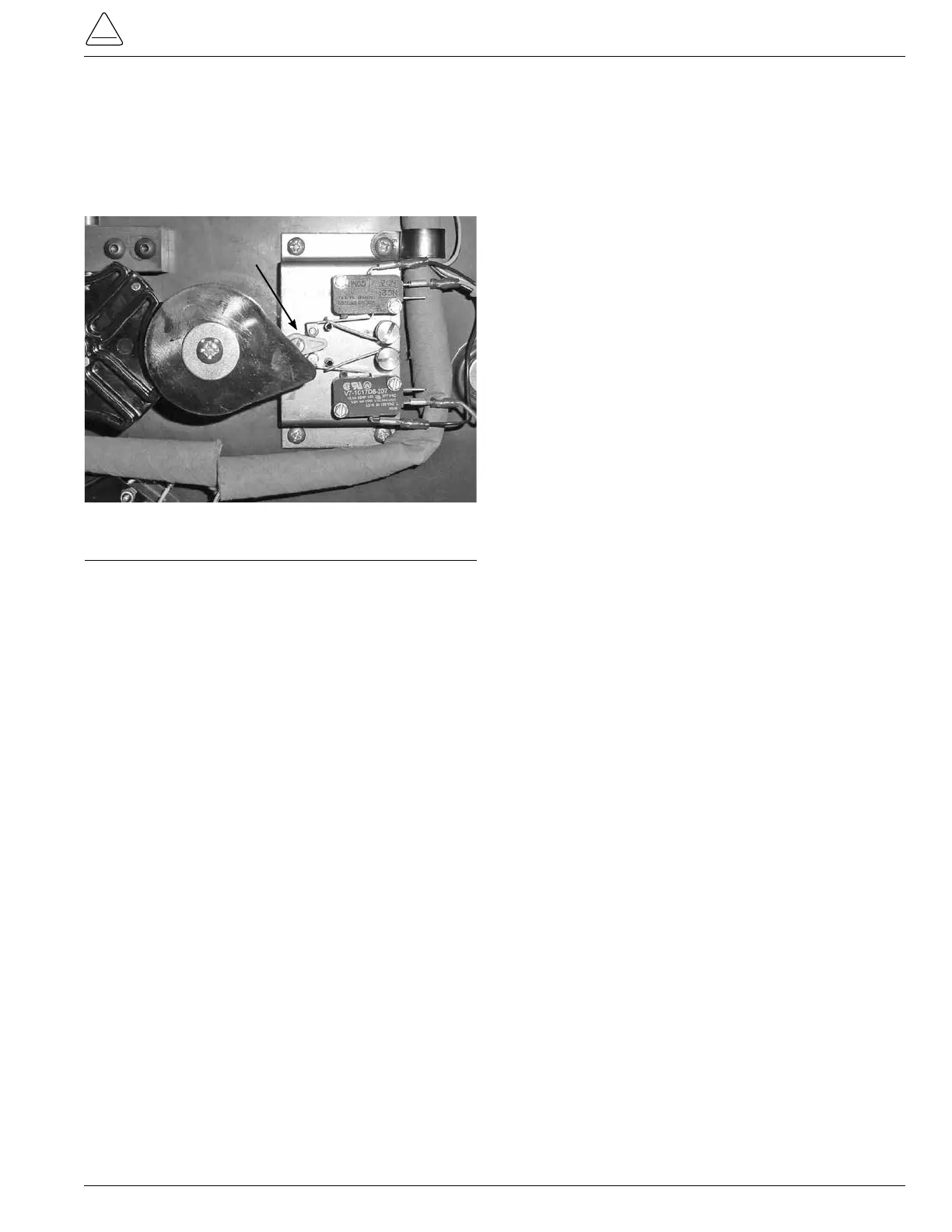
3. Place the holding switch assembly on to the QD3 tap
changer with the nylon actuator located at the 3 o’clock
position or just to he right of the pinion cam. (See Figure
233.)
Figure 233.
Pinion and actuator location.
4.
Using a 9/64 Allen wrench place and tighten the four
mounting screws. (See Figure 232.)
5. Connect the wires on to the holding switch assembly.
(See Figure 232.)
Top Micro Switch
Black wire on top terminal post (com post)
Blue wire on center terminal post (No. 2 post)
Bottom terminal post, vacant (No. 3 post)
Bottom Micro Switch
Top terminal post, vacant (No. 3 post)
Red wire on center terminal post (No. 2 post)
Black wire on bottom terminal post (com post)
Actuator